- 您现在的位置:买卖IC网 > PDF目录20762 > MC10SX1130DR2G (ON Semiconductor)IC LED DRIVER LINEAR 16-SOIC PDF资料下载
参数资料
| 型号: | MC10SX1130DR2G |
| 厂商: | ON Semiconductor |
| 文件页数: | 7/9页 |
| 文件大小: | 0K |
| 描述: | IC LED DRIVER LINEAR 16-SOIC |
| 标准包装: | 2,500 |
| 输出数: | 1 |
| 内部驱动器: | 是 |
| 类型 - 主要: | 通用 |
| 频率: | 300MHz |
| 电源电压: | +5V,-5.2V |
| 安装类型: | 表面贴装 |
| 封装/外壳: | 16-SOIC(0.154",3.90mm 宽) |
| 供应商设备封装: | 16-SOIC |
| 包装: | 带卷 (TR) |
| 工作温度: | -40°C ~ 85°C |
�� �
�
�MC10SX1130�
�First,� the� RSET� resistor� must� be� chosen� to� set� the� desired�
�nominal� modulation� current� based� on� the� following�
�equation:�
�RSET� =� V� SET� /I� MOD� (Equation� 1)�
�The� voltage� at� VSET� is� a� function� of� the� RTCO� tracking�
�resistor,� so� the� desired� tracking� rate� (VTR)� must� also� be�
�chosen.� To� determine� this,� the� equation� must� be� normalized�
�to� correspond� to� how� the� LED� has� been� specified.�
�Temp� Co� =� V� TR� /V� SET� (Equation� 2)�
�The� data� sheet� has� three� temperature� tracking� rates� for�
�different� values� of� the� RTCO� resistor.� By� using� the� V� SET�
�values� at� 25� °� C� and� substituting� those� numbers� into�
�Equation� 2,� normalized� tracking� rates� can� be� calculated.�
�Table� 5.� Normalized� Tracking� at� 25� °� C�
�Thermal� Management�
�LED� devices� tend� to� require� large� amounts� of� current� for�
�most� efficient� operation.� This� requirement� is� then� translated�
�into� the� design� of� the� LED� Driver.� When� large� modulation�
�currents� are� required,� power� dissipation� becomes� a� critical�
�issue� and� the� user� must� be� concerned� about� the� junction�
�temperature� of� the� device.� The� following� equation� can� be�
�used� to� estimate� the� junction� temperature� of� a� device� in� a�
�given� environment:�
�T� J� =� T� A� +� P� D� *� q� JA� (Equation� 3)�
�T� J� Junction� Temperature�
�T� A� Ambient� Temperature�
�P� D� Power� Dissipation�
�q� JA� Average� Thermal� Resistance�
�(Junction-Ambient)�
�A� specially� designed� thermally� enhanced� leadframe� has�
�RTCO�
�Short�
�1� K� W�
�2� K� W�
�Tracking� %/� °� C�
�+0.20�
�+0.52�
�+0.89�
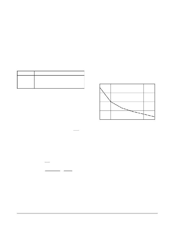
�been� used� to� house� the� LED� Driver.� Below� is� a� graph� of� the�
�average� q� JA� plotted� against� air� flow.�
�110�
�+� 855mV� +� 86mA�
�IMOD(max)� +�
�To� match� the� LED� chosen,� a� 1� k� W� resistor� can� be� used.�
�Now� that� this� is� known,� the� value� of� the� voltage� at� the� V� SET�
�can� be� substituted� into� Equation� 1� to� determine� the� value� of�
�RSET� resistor� which,� for� this� example� is� 10� W� .�
�The� Stretch� circuit� can� be� used� to� compensate� for� the�
�turn-on/turn-off� delay� of� the� LED.� The� circuit� has� been�
�designed� for� ease� of� use� so� the� pin� is� designed� to� be� strapped�
�to� one� of� the� two� power� plane� levels� to� select� the�
�pre-distortion� value.� If� no� pre-distortion� is� desired,� the� pin�
�can� be� left� open.� In� this� +5� V� example,� the� maximum� amount�
�of� pre-distortion� is� desired,� so� the� STRETCH� pin� is�
�connected� to� ground.�
�In� addition� a� resistor� must� be� placed� between� I� OUT� and�
�V� CC� .� In� selecting� this� resistor,� just� as� in� the� case� of� the� RSET,�
�the� resistor� type� should� be� chosen� to� dissipate� the� worst� case�
�power� and� derated� for� the� worst� case� temperature.� As� a� rule�
�of� thumb,� the� voltage� drop� across� the� resistor� should� match�
�the� forward� voltage� across� the� diode.� The� voltage� can� be�
�larger� to� minimize� the� power� dissipated� on� chip� when� the�
�LED� is� not� ’ON’.� Although,� the� voltage� drop� across� this�
�resistor� should� not� be� greater� than� 2� V.� For� this� example:�
�R� @� I� OUT� =� VF/I� MOD�
�VSET@85� °� C�
�RSET� 10� W�
�R� @� I� OUT� =� 1.5V/86mA� =� 17� W�
�100�
�90�
�80�
�70�
�0� 100� 200� 300� 400� 500�
�AIRFLOW� (LFPM)�
�Figure� 4.� Typical� q� JA� versus� Airflow�
�The� power� dissipation� of� the� device� has� two� components;�
�the� quiescent� power� drain� related� to� the� pre-drive� circuitry,�
�and� the� power� dissipated� in� the� current� switch� when� driving�
�the� LED.�
�Pd� =� Pstatic� +� Pswitching� (Equation� 4)�
�The� power� dissipated� in� the� current� switch� is� a� function� of�
�the� IMOD� current,� the� LED� forward� voltage,� and� the� value�
�of� RSET.� For� example� in� a� +5� V� application,� the� following�
�equations� can� be� used:�
�Pstatic� =� V� CC� *� I� CC� (Equation� 5)�
�Pswitching� =� (V� CC� -V� F� -V� SET� )*� I� MOD� (Equation� 6)�
�Because� of� the� positive� tracking� circuitry� in� the� LED�
�driver,� the� modulation� current� will� increase� over�
�temperature.� It� is� important� to� now� go� back� and� re-calculate�
�the� numbers� under� the� worst� case� environmental� conditions�
�to� ensure� that� operating� conditions� have� not� been� exceeded.�
�http://onsemi.com�
�7�
�相关PDF资料 |
PDF描述 |
|---|---|
| RBC07DRYH | CONN EDGECARD 14POS DIP .100 SLD |
| ACE50DHRD | CONN CARD EXTEND 100POS 1MM SLD |
| RBC06DCMS | CONN EDGECARD 12POS .100 WW |
| GEC15DRYS | CONN EDGECARD 30POS DIP .100 SLD |
| ACB35DHAN | CONN EDGECARD 70POS R/A .050 DIP |
相关代理商/技术参数 |
参数描述 |
|---|---|
| MC10SX1189D | 功能描述:缓冲器和线路驱动器 Fiber Channel Coax RoHS:否 制造商:Micrel 输入线路数量:1 输出线路数量:2 极性:Non-Inverting 电源电压-最大:+/- 5.5 V 电源电压-最小:+/- 2.37 V 最大工作温度:+ 85 C 安装风格:SMD/SMT 封装 / 箱体:MSOP-8 封装:Reel |
| MC10SX1189DG | 功能描述:缓冲器和线路驱动器 Fiber Channel Coax Calbe Driver RoHS:否 制造商:Micrel 输入线路数量:1 输出线路数量:2 极性:Non-Inverting 电源电压-最大:+/- 5.5 V 电源电压-最小:+/- 2.37 V 最大工作温度:+ 85 C 安装风格:SMD/SMT 封装 / 箱体:MSOP-8 封装:Reel |
| MC10SX1189DR2 | 功能描述:缓冲器和线路驱动器 Fiber Channel Coax RoHS:否 制造商:Micrel 输入线路数量:1 输出线路数量:2 极性:Non-Inverting 电源电压-最大:+/- 5.5 V 电源电压-最小:+/- 2.37 V 最大工作温度:+ 85 C 安装风格:SMD/SMT 封装 / 箱体:MSOP-8 封装:Reel |
| MC10SX1189DR2G | 功能描述:缓冲器和线路驱动器 Fiber Channel Coax Calbe Driver RoHS:否 制造商:Micrel 输入线路数量:1 输出线路数量:2 极性:Non-Inverting 电源电压-最大:+/- 5.5 V 电源电压-最小:+/- 2.37 V 最大工作温度:+ 85 C 安装风格:SMD/SMT 封装 / 箱体:MSOP-8 封装:Reel |
| MC10SX1190DT | 功能描述:缓冲器和线路驱动器 Fiber Channel Coax RoHS:否 制造商:Micrel 输入线路数量:1 输出线路数量:2 极性:Non-Inverting 电源电压-最大:+/- 5.5 V 电源电压-最小:+/- 2.37 V 最大工作温度:+ 85 C 安装风格:SMD/SMT 封装 / 箱体:MSOP-8 封装:Reel |
发布紧急采购,3分钟左右您将得到回复。