- 您现在的位置:买卖IC网 > PDF目录80565 > MC68HC681FN (FREESCALE SEMICONDUCTOR INC) 2 CHANNEL(S), 1M bps, SERIAL COMM CONTROLLER, PQCC44 PDF资料下载
参数资料
| 型号: | MC68HC681FN |
| 厂商: | FREESCALE SEMICONDUCTOR INC |
| 元件分类: | 微控制器/微处理器 |
| 英文描述: | 2 CHANNEL(S), 1M bps, SERIAL COMM CONTROLLER, PQCC44 |
| 封装: | PLASTIC, LCC-44 |
| 文件页数: | 30/88页 |
| 文件大小: | 726K |
| 代理商: | MC68HC681FN |
第1页第2页第3页第4页第5页第6页第7页第8页第9页第10页第11页第12页第13页第14页第15页第16页第17页第18页第19页第20页第21页第22页第23页第24页第25页第26页第27页第28页第29页当前第30页第31页第32页第33页第34页第35页第36页第37页第38页第39页第40页第41页第42页第43页第44页第45页第46页第47页第48页第49页第50页第51页第52页第53页第54页第55页第56页第57页第58页第59页第60页第61页第62页第63页第64页第65页第66页第67页第68页第69页第70页第71页第72页第73页第74页第75页第76页第77页第78页第79页第80页第81页第82页第83页第84页第85页第86页第87页第88页
Programming and Register Descriptions
4-6
MC68HC681 USER’S MANUAL
MOTOROLA
4
Similarly, certain changes to the auxiliary control register (ACR bits six through four)
should only be made while the counter/timer (C/T) is not used (i.e., stopped if in counter
mode, output and/or interrupt masked in timer mode).
Channel A mode registers MR1A and MR2A are accessed via an auxiliary pointer. The
pointer is set to mode register one (MR1A) by RESET or by issuing a "reset pointer"
command via the channel A command register. Any read or write of the mode register
switches the pointer to mode register two (MR2A). All subsequent accesses will address
MR2A unless the pointer is reset to MR1A as described above. The channel B mode
registers MR1B and MR2B are accessed by an identical pointer independent of the
channel A pointer. Mode, command, clock-select, and status registers are duplicated for
each channel to allow independent operation and control (except that both channels are
restricted to baud rates that are in the same set).
4.2 REGISTER BIT FORMATS
Rx RTR—Control
0 = Disabled
1 = Enabled
Rx IRQ = Select
0 = RxRDY
1 = FFULL
Error Mode
0 = Character
1 = Block
Parity Mode (Bits 4 and 3)
0 0 = With Parity
0 1 = Force Parity
1 0 = No Parity
1 1 = Multidrop Mode
Parity Type
With Parity
0 = Even
1 = Odd
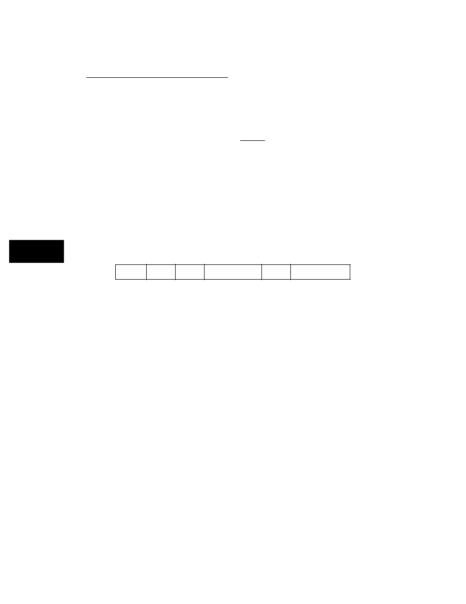
Channel A/B Mode Register 1 (MR1A/MR1B)
7
654321
0
RX RTR
RX IRQ
ERROR
MODE
PARITY MODE
PARITY
TYPE
BITS PER CHARACTER
F
re
e
sc
a
le
S
e
m
ic
o
n
d
u
c
to
r,
I
Freescale Semiconductor, Inc.
For More Information On This Product,
Go to: www.freescale.com
n
c
..
.
相关PDF资料 |
PDF描述 |
|---|---|
| MC68040RC25 | 32-BIT, 25 MHz, MICROPROCESSOR, CPGA179 |
| MC68EC040RC33B | 32-BIT, 33 MHz, MICROPROCESSOR, CPGA179 |
| MC68EN360CRC25 | RISC MICROCONTROLLER, CPGA241 |
| MC9S08SH8CFKR | MICROCONTROLLER, PQCC24 |
| MC9S12XS64J1MAL | 16-BIT, FLASH, 40 MHz, MICROCONTROLLER, PQFP112 |
相关代理商/技术参数 |
参数描述 |
|---|---|
| MC68HC68T1P | 制造商:Motorola Inc 功能描述: |
| MC68HC705B16CFN | 制造商:Motorola Inc 功能描述: |
| MC68HC705B16FN | 制造商:Rochester Electronics LLC 功能描述: |
| MC68HC705B16NB | 制造商:Rochester Electronics LLC 功能描述: |
| MC68HC705B16NCB | 制造商:Rochester Electronics LLC 功能描述: |
发布紧急采购,3分钟左右您将得到回复。