- 您现在的位置:买卖IC网 > PDF目录80341 > MC80C32-12SB (ATMEL CORP) 8-BIT, 12 MHz, MICROCONTROLLER, CDIP40 PDF资料下载
参数资料
| 型号: | MC80C32-12SB |
| 厂商: | ATMEL CORP |
| 元件分类: | 微控制器/微处理器 |
| 英文描述: | 8-BIT, 12 MHz, MICROCONTROLLER, CDIP40 |
| 封装: | 0.600 INCH, SIDE BRAZED, DIP-40 |
| 文件页数: | 22/46页 |
| 文件大小: | 7004K |
| 代理商: | MC80C32-12SB |
第1页第2页第3页第4页第5页第6页第7页第8页第9页第10页第11页第12页第13页第14页第15页第16页第17页第18页第19页第20页第21页当前第22页第23页第24页第25页第26页第27页第28页第29页第30页第31页第32页第33页第34页第35页第36页第37页第38页第39页第40页第41页第42页第43页第44页第45页第46页
154
7593L–AVR–09/12
AT90USB64/128
output can be generated by setting the COM2x1:0 to three. TOP is defined as 0xFF when
WGM2:0 = 3, and OCR2A when MGM2:0 = 7 (see Table 16-3 on page 157). The actual OC2x
value will only be visible on the port pin if the data direction for the port pin is set as output. The
PWM waveform is generated by clearing (or setting) the OC2x Register at the compare match
between OCR2x and TCNT2 when the counter increments, and setting (or clearing) the OC2x
Register at compare match between OCR2x and TCNT2 when the counter decrements. The
PWM frequency for the output when using phase correct PWM can be calculated by the follow-
ing equation:
The N variable represents the prescale factor (1, 8, 32, 64, 128, 256, or 1024).
The extreme values for the OCR2A Register represent special cases when generating a PWM
waveform output in the phase correct PWM mode. If the OCR2A is set equal to BOTTOM, the
output will be continuously low and if set equal to MAX the output will be continuously high for
non-inverted PWM mode. For inverted PWM the output will have the opposite logic values.
At the very start of period 2 in Figure 16-7 on page 153 OCnx has a transition from high to low
even though there is no Compare Match. The point of this transition is to guarantee symmetry
around BOTTOM. There are two cases that give a transition without Compare Match.
OCR2A changes its value from MAX, like in Figure 16-7 on page 153. When the OCR2A
value is MAX the OCn pin value is the same as the result of a down-counting compare match.
To ensure symmetry around BOTTOM the OCn value at MAX must correspond to the result
of an up-counting Compare Match
The timer starts counting from a value higher than the one in OCR2A, and for that reason
misses the Compare Match and hence the OCn change that would have happened on the
way up
16.7
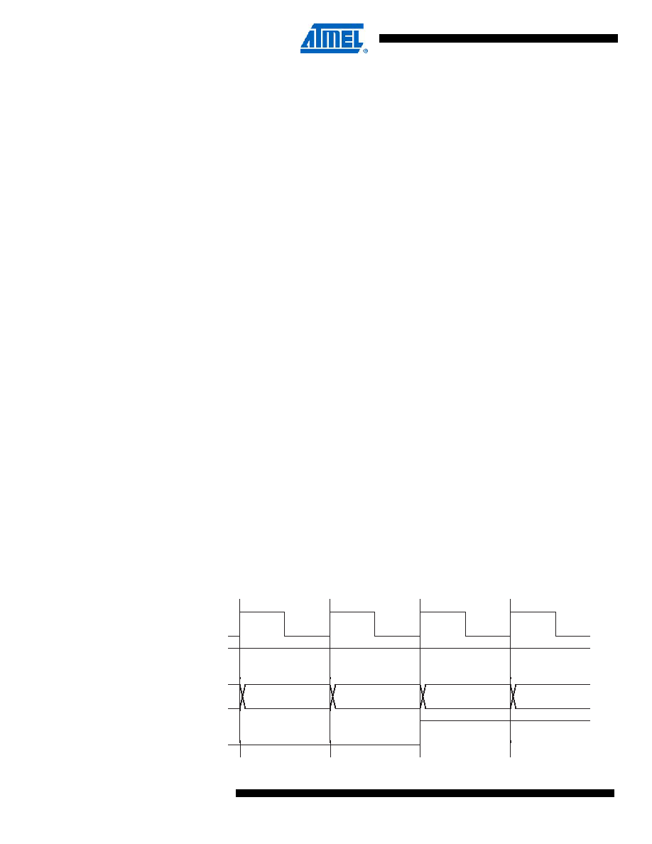
Timer/Counter timing diagrams
The following figures show the Timer/Counter in synchronous mode, and the timer clock (clk
T2)
is therefore shown as a clock enable signal. In asynchronous mode, clk
I/O should be replaced by
the Timer/Counter Oscillator clock. The figures include information on when Interrupt Flags are
set. Figure 16-8 contains timing data for basic Timer/Counter operation. The figure shows the
count sequence close to the MAX value in all modes other than phase correct PWM mode.
Figure 16-8. Timer/Counter timing diagram, no prescaling.
fOCnxPCPWM
f
clk_I/O
N 510
------------------
=
clk
Tn
(clk
I/O/1)
TOVn
clk
I/O
TCNTn
MAX - 1
MAX
BOTTOM
BOTTOM + 1
相关PDF资料 |
PDF描述 |
|---|---|
| MC80C52EXXX-12SCD | 8-BIT, MROM, 12 MHz, MICROCONTROLLER, CDIP40 |
| MR80C52TXXX-12P883D | 8-BIT, MROM, 12 MHz, MICROCONTROLLER, CQCC44 |
| MR80C52TXXX-12SBD | 8-BIT, MROM, 12 MHz, MICROCONTROLLER, CQCC44 |
| MD80C52EXXX-30/883D | 8-BIT, MROM, 30 MHz, MICROCONTROLLER, CDIP40 |
| MR80C52TXXX-30SC | 8-BIT, MROM, 30 MHz, MICROCONTROLLER, CQCC44 |
相关代理商/技术参数 |
参数描述 |
|---|---|
| MC-80C32E-30 | 制造商:AIMTEC 制造商全称:AIMTEC 功能描述:Rad. Tolerant 8-bit ROMless Microcontroller |
| MC-80C32E-30-E | 制造商:AIMTEC 制造商全称:AIMTEC 功能描述:Rad. Tolerant 8-bit ROMless Microcontroller |
| MC80D21000G | 制造商:COR 功能描述:RN |
| MC80F0104 | 制造商:未知厂家 制造商全称:未知厂家 功能描述:8-BIT SINGLE-CHIP MICROCONTROLLERS |
| MC80F0104B | 制造商:未知厂家 制造商全称:未知厂家 功能描述:8-BIT SINGLE-CHIP MICROCONTROLLERS |
发布紧急采购,3分钟左右您将得到回复。