- 您现在的位置:买卖IC网 > PDF目录11663 > MC9S08SF4MTJ (Freescale Semiconductor)MCU 8BIT 4K FLASH 20-TSSOP PDF资料下载
参数资料
| 型号: | MC9S08SF4MTJ |
| 厂商: | Freescale Semiconductor |
| 文件页数: | 27/30页 |
| 文件大小: | 0K |
| 描述: | MCU 8BIT 4K FLASH 20-TSSOP |
| 标准包装: | 75 |
| 系列: | S08 |
| 核心处理器: | S08 |
| 芯体尺寸: | 8-位 |
| 速度: | 40MHz |
| 连通性: | I²C |
| 外围设备: | LVD,POR,PWM,WDT |
| 输入/输出数: | 18 |
| 程序存储器容量: | 4KB(4K x 8) |
| 程序存储器类型: | 闪存 |
| RAM 容量: | 128 x 8 |
| 电压 - 电源 (Vcc/Vdd): | 2.7 V ~ 5.5 V |
| 数据转换器: | A/D 8x10b |
| 振荡器型: | 外部 |
| 工作温度: | -40°C ~ 125°C |
| 封装/外壳: | 20-TSSOP(0.173",4.40mm 宽) |
| 包装: | 管件 |
第1页第2页第3页第4页第5页第6页第7页第8页第9页第10页第11页第12页第13页第14页第15页第16页第17页第18页第19页第20页第21页第22页第23页第24页第25页第26页当前第27页第28页第29页第30页
MC9S08SF4 Series MCU Data Sheet, Rev. 4
Thermal Characteristics
Freescale Semiconductor
6
3.4
Thermal Characteristics
This section provides information about operating temperature range, power dissipation, and package
thermal resistance. Power dissipation on I/O pins is usually small compared to the power dissipation in
on-chip logic and voltage regulator circuits and it is user-determined rather than being controlled by the
MCU design. To take PI/O into account in power calculations, determine the difference between actual pin
voltage and VSS or VDD and multiply by the pin current for each I/O pin. Except in cases of unusually high
pin current (heavy loads), the difference between pin voltage and VSS or VDD will be small.
The average chip-junction temperature (TJ) in C can be obtained from:
TJ = TA + (PD JA)
Eqn. 1
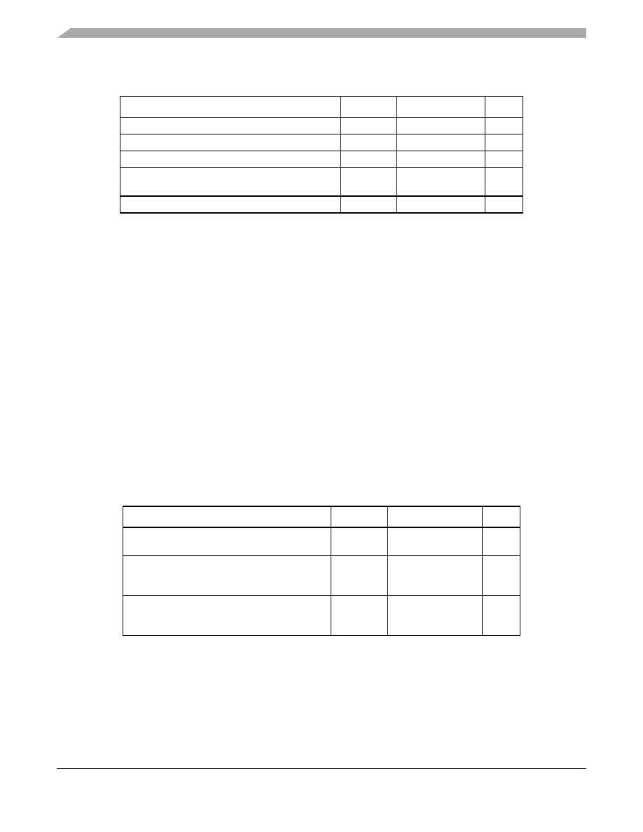
Table 2. Absolute Maximum Ratings
Rating
Symbol
Value
Unit
Supply voltage
VDD
–0.3 to 5.8
V
Maximum current into VDD
IDD
120
mA
Digital input voltage
VIn
–0.3 to VDD +0.3
V
Instantaneous maximum current
Single pin limit (applies to all port pins)1, 2, 3
1
Input must be current limited to the value specified. To determine the value of the required
current-limiting resistor, calculate resistance values for positive (VDD) and negative (VSS) clamp
voltages, then use the larger of the two resistance values.
2 All functional non-supply pins are internally clamped to V
SS and VDD.
3 Power supply must maintain regulation within operating V
DD range during instantaneous and
operating maximum current conditions. If positive injection current (VIn > VDD) is greater than
IDD, the injection current may flow out of VDD and could result in the external power supply going
out of regulation. Ensure external VDD load shunts current greater than the maximum injection
current. This will be the greatest risk when the MCU is not consuming power. Examples are: if
no system clock is present, or if the clock rate is very low (which would reduce overall power
consumption).
ID
25
mA
Storage temperature range
Tstg
–55 to 150
C
Table 3. Thermal Characteristics
Rating
Symbol
Value
Unit
Operating temperature range
(packaged)
TA
TL to TH
–40 to 125
C
Thermal resistance (single-layer board)
20-pin TSSOP
16-pin TSSOP
JA
115
123
C/W
Thermal resistance (four-layer board)
20-pin TSSOP
16-pin TSSOP
JA
76
75
C/W
相关PDF资料 |
PDF描述 |
|---|---|
| MC9S08QE4CWJ | IC MCU 8BIT 4K FLASH 20-SOIC |
| MC9S08SH4CWJ | MCU 8BIT 4K FLASH 20-SOIC |
| MC9S08JS8CWJ | IC MCU 8BIT 8K FLASH 20SOIC |
| 8-227079-1 | PLUG, COML BNC, KIT |
| MC9S08JS8CFK | IC MCU 8BIT 8K FLASH 24QFN |
相关代理商/技术参数 |
参数描述 |
|---|---|
| MC9S08SF4VTG | 制造商:FREESCALE 制造商全称:Freescale Semiconductor, Inc 功能描述:Technical Data |
| MC9S08SF4VTJ | 制造商:FREESCALE 制造商全称:Freescale Semiconductor, Inc 功能描述:Technical Data |
| MC9S08SG16 | 制造商:FREESCALE 制造商全称:Freescale Semiconductor, Inc 功能描述:HCS08 Microcontrollers |
| MC9S08SG16E1CTGR | 制造商:FREESCALE 制造商全称:Freescale Semiconductor, Inc 功能描述:HCS08 Microcontrollers |
| MC9S08SG16E1CTJR | 制造商:FREESCALE 制造商全称:Freescale Semiconductor, Inc 功能描述:HCS08 Microcontrollers |
发布紧急采购,3分钟左右您将得到回复。