- 您现在的位置:买卖IC网 > PDF目录2097 > MCP3221A5T-E/OT (Microchip Technology)IC ADC 12BIT 2.7V 1CH LP SOT23-5 PDF资料下载
参数资料
| 型号: | MCP3221A5T-E/OT |
| 厂商: | Microchip Technology |
| 文件页数: | 8/28页 |
| 文件大小: | 0K |
| 描述: | IC ADC 12BIT 2.7V 1CH LP SOT23-5 |
| 标准包装: | 1 |
| 位数: | 12 |
| 采样率(每秒): | 22.3k |
| 数据接口: | I²C,串行 |
| 转换器数目: | 1 |
| 电压电源: | 单电源 |
| 工作温度: | -40°C ~ 125°C |
| 安装类型: | 表面贴装 |
| 封装/外壳: | SC-74A,SOT-753 |
| 供应商设备封装: | SOT-23-5 |
| 包装: | 标准包装 |
| 输入数目和类型: | 1 个单端,单极 |
| 产品目录页面: | 672 (CN2011-ZH PDF) |
| 配用: | VSUPEV2-ND - BOARD EVAL FOR MCP4022,4023,4024 MXSIGDM-ND - BOARD DEMO PICTAIL MIXED SIGNAL |
| 其它名称: | MCP3221A5T-E/OTDKR |
第1页第2页第3页第4页第5页第6页第7页当前第8页第9页第10页第11页第12页第13页第14页第15页第16页第17页第18页第19页第20页第21页第22页第23页第24页第25页第26页第27页第28页
MCP3221
DS21732C-page 16
2006 Microchip Technology Inc.
5.2
Device Addressing
The address byte is the first byte received following the
START condition from the master device. The first part
of the control byte consists of a 4-bit device code, which
is set to 1001 for the MCP3221. The device code is fol-
lowed by three address bits: A2, A1 and A0. The default
address bits are 101. Contact the Microchip factory for
additional address bit options. The address bits allow
up to eight MCP3221 devices on the same bus and are
used to determine which device is accessed.
The eighth bit of the slave address determines if the
master device wants to read conversion data or write to
the MCP3221. When set to a ‘1’, a read operation is
selected. When set to a ‘0’, a write operation is
selected. There are no writable registers on the
MCP3221. Therefore, this bit must be set to a ’1’ in
order to initiate a conversion.
The MCP3221 is a slave device that is compatible with
the I2C 2-wire serial interface protocol. A hardware
connection diagram is shown in Figure 6-2. Communi-
cation is initiated by the microcontroller (master
device), which sends a START bit followed by the
address byte.
On completion of the conversion(s) performed by the
MCP3221, the microcontroller must send a STOP bit to
end communication.
The last bit in the device address byte is the R/W bit.
When this bit is a logic ‘1’, a conversion will be exe-
cuted. Setting this bit to logic ‘0’ will also result in an
“acknowledge” (ACK) from the MCP3221, with the
device then releasing the bus. This can be used for
device polling. Refer to Section 6.3 “Device Polling”,
“Device Polling”, for more information.
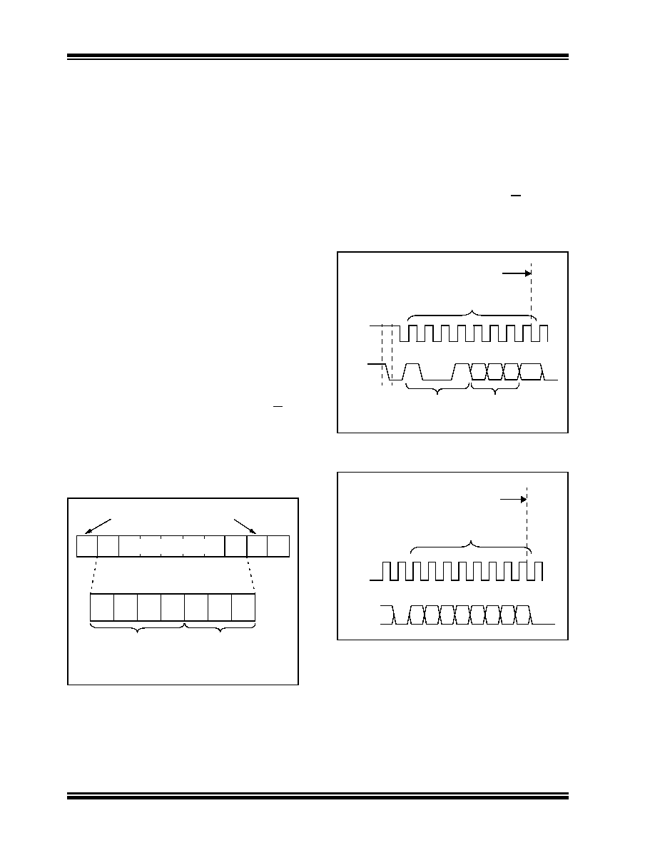
FIGURE 5-2:
Device Addressing.
5.3
Executing a Conversion
This section will describe the details of communicating
with the MCP3221 device. Initiating the sample-and-
hold acquisition, reading the conversion data and
executing multiple conversions will be discussed.
5.3.1
INITIATING THE SAMPLE AND
HOLD
The acquisition and conversion of the input signal
begins with the falling edge of the R/W bit of the
address byte. At this point, the internal clock initiates
the sample, hold and conversion cycle, all of which are
internal to the ADC.
FIGURE 5-3:
Initiating the Conversion,
Address Byte.
FIGURE 5-4:
Initiating the Conversion,
Continuous Conversions.
START
READ/WRITE
SLAVE ADDRESS
R/W A
1
0
1
0
1
Address Bits(1)
Note 1: Contact Microchip for additional address bits.
Device Code
1
234
56
7
8
9
SCL
SDA
1 0
0 1 A2 A1 A0 R/W
ACK
Start
Bit
Address Byte
Address bits
Device bits
tACQ + tCONV is
initiated here
SCL
SDA
D3 D2 D2
ACK
Lower Data Byte (n)
tACQ + tCONV is
initiated here
D6 D5 D4
D0
D7
ACK
D8
17 18 19 20 21 22 23 24 25 26
相关PDF资料 |
PDF描述 |
|---|---|
| MCP3302-BI/SL | IC ADC 13BIT 2.7V 2CH SPI 14SOIC |
| MCP3421A0T-E/CH | IC ADC 18BIT 3.75SPS 1CH SOT23-6 |
| MCP3421A0T-E/OT | IC ADC 18BIT 3.75SPS 1CH SOT23-6 |
| MCP3424T-E/ST | IC ADC 18BIT 3.75SPS 4CH 14TSSOP |
| MCP3425A0T-E/CH | IC ADC 16BIT I2C PROGBL SOT23-6 |
相关代理商/技术参数 |
参数描述 |
|---|---|
| MCP3221A5T-I/OT | 功能描述:模数转换器 - ADC 10-bit I2C Sgl Chl RoHS:否 制造商:Texas Instruments 通道数量:2 结构:Sigma-Delta 转换速率:125 SPs to 8 KSPs 分辨率:24 bit 输入类型:Differential 信噪比:107 dB 接口类型:SPI 工作电源电压:1.7 V to 3.6 V, 2.7 V to 5.25 V 最大工作温度:+ 85 C 安装风格:SMD/SMT 封装 / 箱体:VQFN-32 |
| MCP3221A5T-I/OT | 制造商:Microchip Technology Inc 功能描述:A/D Converter (A-D) IC |
| MCP3221A5T-I/OT-CUT TAPE | 制造商:Microchip 功能描述:Single Channel I2C Interface 2.7 V 12-Bit A/D Converter SMT - SOT-23-5 |
| MCP3221A6-E/OT | 制造商:MICROCHIP 制造商全称:Microchip Technology 功能描述:Low Power 12-Bit A/D Converter With I2C⑩ Interface |
| MCP3221A6-I/OT | 制造商:MICROCHIP 制造商全称:Microchip Technology 功能描述:Low Power 12-Bit A/D Converter With I2C⑩ Interface |
发布紧急采购,3分钟左右您将得到回复。