- 您现在的位置:买卖IC网 > PDF目录296559 > MIC2591B-5YTQ (MICREL INC) 1-CHANNEL POWER SUPPLY SUPPORT CKT, PQFP48 PDF资料下载
参数资料
| 型号: | MIC2591B-5YTQ |
| 厂商: | MICREL INC |
| 元件分类: | 电源管理 |
| 英文描述: | 1-CHANNEL POWER SUPPLY SUPPORT CKT, PQFP48 |
| 封装: | LEAD FREE, TQFP-48 |
| 文件页数: | 9/34页 |
| 文件大小: | 1920K |
| 代理商: | MIC2591B-5YTQ |
第1页第2页第3页第4页第5页第6页第7页第8页当前第9页第10页第11页第12页第13页第14页第15页第16页第17页第18页第19页第20页第21页第22页第23页第24页第25页第26页第27页第28页第29页第30页第31页第32页第33页第34页
March 2005
17
M9999-033105
MIC2591B
Micrel
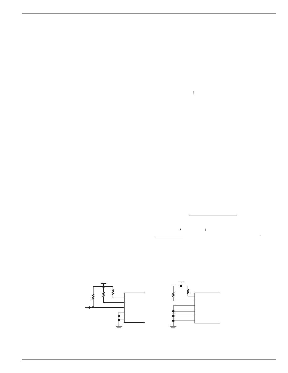
Figure 6. Input Pin Conguration for Disabling HPI/SMI Control
Functional Description
Hot Swap Insertion
When circuit boards are inserted into systems carrying live
supply voltages (“hot-plugged”), high inrush currents often
result due to the charging of bulk capacitance that resides
across the circuit board’s supply pins. This transient inrush
current can cause the system’s supply voltages to temporarily
go out of regulation, causing data loss or system lock-up. In
more extreme cases, the transients occurring during a hot-
plug event may cause permanent damage to connectors or
on-board components.
The MIC2591B addresses these issues by limiting the in-
rush currents to the load (PCI Express Board), and thereby
controlling the rate at which the load’s circuits turn-on. In
addition to this inrush current control, the MIC2591B offers
input and output voltage supervisory functions and current
limiting to provide robust protection for both the system and
circuit board.
System Interface
The MIC2591B employs two system interfaces: the hard-
ware Hot-Plug Interface (HPI) and the System Management
Interface (SMI). The HPI includes ON[A/B], AUXEN[A/B],
as well as /FAULT[A/B]; the SMI consists of SDA, SCL,
and /INT, whose signals conform to the levels and timing of
the SMBus specication. The MIC2591B can be operated
exclusively from the SMI, or can employ the HPl for power
control while continuing to use the SMI for access to all but
the power control registers.
InadditiontothebasicpowercontrolfeaturesoftheMIC2591B
accessible by the HPI, the SMI also gives the host access to
the following information from the part:
Output voltage and current from each supply.
Fault conditions occurring on each supply.
GPI_[A0/B0] pin status.
When using the System Management Interface for power
control, do not use the Hot-Plug Interface. Conversely, when
using the Hot-Plug Interface for power control, do not execute
power control commands over the System Management
Interface bus (all other register accesses via the SMI bus
remain permissible while in the HPI control mode). When
utilizing the SMI exclusively, the HPI input pins (ON[A/B],
AUXEN[A/B], and /FORCE_ON[A/B] should be congured
as shown below in Figure 6 (Disabling HPI when SMI control
is used). This conguration safeguards the power slots in the
event that the SMBus communication link is disconnected
for any reason.
Additionally, when utilizing the HPI exclusively, the SMBus
(or SMI) will be inactive if the input pins (SDA, SCL, A0, A1,
andA2) are congured as shown in Figure 6 below (Disabling
SMI when HPI Control is used).
Power Stability and Power-On Reset
The MIC2591B utilizes VSTBY[A/B] as the main supply input
source. VSTBY[A/B] is required for proper operation of the
MIC2591B’s SMBus and registers and must be applied at
all times. To ensure that the MIC2591B controller operates
properly, the VSTBY input must be stable and remain above
STBY
the undervoltage lockout (UVLO) threshold once applied.
Sufcient input bulk capacitance should be used to prevent
the supply from "drooping", causing VSTBY[A/B] to fall below
the UVLO threshold. Also, decoupling capacitors should be
placed at each of the MIC2591B inputs in order to lter high
frequency noise transients.
VSTBY must be the rst supply input applied followed by the
STBY
MAIN supply inputs of 12VIN and 3VIN. A Power-On Reset
(POR) cycle is initiated after VSTBY[A/B] rises above its
UVLO threshold and remains valid at that voltage for 250s.
All internal registers are cleared after POR. If VSTBY[A/B] is
recycled, the MIC2591B enters a new power-on-reset cycle.
The SMBus is ready for access at the end of the POR cycle
(250s after VSTBY[A/B] is valid). During tPOR, all outputs
remain off. In most applications, the total POR interval will
consist of the time required to charge the VSTBY input (by-
STBY
pass) capacitance to the UVLO threshold plus the internal
tPOR. The following equation is used to approximate the total
POR interval:
tPOR_TOTAL(S) =
CSTBY(F) VULVO(STBY)
ICHARGE(STBY)(A)
tPOR(S)
10 6
where CSTBYis the V
STBY
STBY input bulk bypass capacitance and
STBY
ICHARGE(STBY) is the current supplied by the VSTBY source
STBY
to charge the capacitance.
CHARGE(STBY)
Power-Up Cycle
Enabling the GATE output
When a slot's MAIN supplies are off, the 12VGATE pin is held
high with an internal pull-up. Similarly, the 3VGATE pin is
internally held low. When the MAIN supplies of the MIC2591B
MIC2591B
A2
/INT
SDA
SCL
A0
VSTBY
A1
100k
47
48
37
39
40
41
100k
Disabling SMI when
HPI Control is used
Disabling HPI when
SMI Control is used
100k
/INT
/FORCE_ONB
100k
/FORCE_ONA
AUXENA
AUXENB
ONA
ONB
MIC2591B
9
28
45
42
44
43
相关PDF资料 |
PDF描述 |
|---|---|
| MIC30711-5100W-LF3 | 32 CONTACT(S), FEMALE, RIGHT ANGLE TELECOM AND DATACOM CONNECTOR, SOLDER |
| MIC3730-1.8BR | 1.8 V FIXED POSITIVE LDO REGULATOR, 0.5 V DROPOUT, PSSO5 |
| MIC5225-1.5YM5TR | 1.5 V FIXED POSITIVE LDO REGULATOR, 0.45 V DROPOUT, PDSO5 |
| MIC5225-2.5YM5TR | 2.5 V FIXED POSITIVE LDO REGULATOR, 0.45 V DROPOUT, PDSO5 |
| MIC5225-3.3YM5TR | 3.3 V FIXED POSITIVE LDO REGULATOR, 0.45 V DROPOUT, PDSO5 |
相关代理商/技术参数 |
参数描述 |
|---|---|
| MIC2592B-2BTQ | 功能描述:IC CTRLR HOTPLUG PCI DUAL 48TQFP RoHS:否 类别:集成电路 (IC) >> PMIC - 热交换 系列:- 产品培训模块:Obsolescence Mitigation Program 标准包装:100 系列:- 类型:热插拔开关 应用:通用 内部开关:是 电流限制:可调 电源电压:9 V ~ 13.2 V 工作温度:-40°C ~ 150°C 安装类型:表面贴装 封装/外壳:10-WFDFN 裸露焊盘 供应商设备封装:10-TDFN-EP(3x3) 包装:管件 |
| MIC2592B-2BTQ TR | 功能描述:IC PCI HOT PLUG CTLR DUAL 48TQFP RoHS:否 类别:集成电路 (IC) >> PMIC - 热交换 系列:- 产品培训模块:Obsolescence Mitigation Program 标准包装:100 系列:- 类型:热插拔开关 应用:通用 内部开关:是 电流限制:可调 电源电压:9 V ~ 13.2 V 工作温度:-40°C ~ 150°C 安装类型:表面贴装 封装/外壳:10-WFDFN 裸露焊盘 供应商设备封装:10-TDFN-EP(3x3) 包装:管件 |
| MIC2592B-2YTQ | 功能描述:热插拔功率分布 Dual-slot PCI-Express Hot Swap Power Controller - Lead Free RoHS:否 制造商:Texas Instruments 产品:Controllers & Switches 电流限制: 电源电压-最大:7 V 电源电压-最小:- 0.3 V 工作温度范围: 功率耗散: 安装风格:SMD/SMT 封装 / 箱体:MSOP-8 封装:Tube |
| MIC2592B-2YTQ TR | 功能描述:热插拔功率分布 Dual-slot PCI-Express Hot Swap Power Controller - Lead Free RoHS:否 制造商:Texas Instruments 产品:Controllers & Switches 电流限制: 电源电压-最大:7 V 电源电压-最小:- 0.3 V 工作温度范围: 功率耗散: 安装风格:SMD/SMT 封装 / 箱体:MSOP-8 封装:Tube |
| MIC2593-2BTQ | 功能描述:IC CTRLR HOTPLUG PCI DUAL 48TQFP RoHS:否 类别:集成电路 (IC) >> PMIC - 热交换 系列:- 产品培训模块:Obsolescence Mitigation Program 标准包装:100 系列:- 类型:热插拔开关 应用:通用 内部开关:是 电流限制:可调 电源电压:9 V ~ 13.2 V 工作温度:-40°C ~ 150°C 安装类型:表面贴装 封装/外壳:10-WFDFN 裸露焊盘 供应商设备封装:10-TDFN-EP(3x3) 包装:管件 |
发布紧急采购,3分钟左右您将得到回复。