- 您现在的位置:买卖IC网 > PDF目录45328 > MK2069-03GITR (INTEGRATED DEVICE TECHNOLOGY INC) 160 MHz, OTHER CLOCK GENERATOR, PDSO56 PDF资料下载
参数资料
| 型号: | MK2069-03GITR |
| 厂商: | INTEGRATED DEVICE TECHNOLOGY INC |
| 元件分类: | 时钟产生/分配 |
| 英文描述: | 160 MHz, OTHER CLOCK GENERATOR, PDSO56 |
| 封装: | 6.10 MM, 0.50 MM PITCH, TSSOP-56 |
| 文件页数: | 3/20页 |
| 文件大小: | 204K |
| 代理商: | MK2069-03GITR |
MK2069-03
VCXO-BASED CLOCK TRANSLATOR WITH HIGH MULTIPLICATION
VCXO AND SYNTHESIZER
IDT / ICS VCXO-BASED CLOCK TRANSLATOR WITH HIGH MULTIPLICATION 11
MK2069-03
REV J 030906
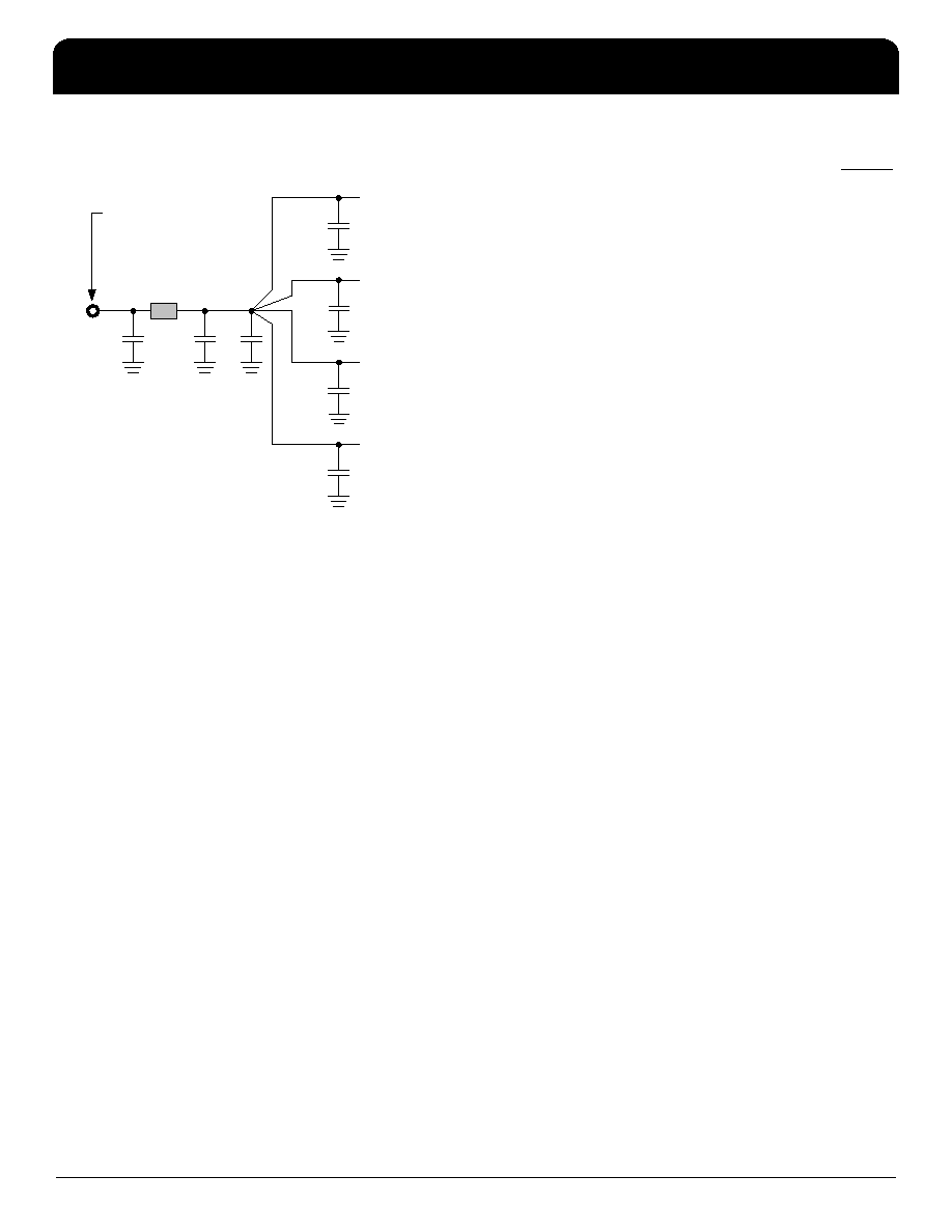
Recommended Power Supply Connection
Series Termination Resistor
Output clock PCB traces over 1 inch should use series
termination to maintain clock signal integrity and to reduce
EMI. To series terminate a 50
Ω trace, which is a commonly
used PCB trace impedance, place a 33
Ω resistor in series
with the clock line as close to the clock output pin as
possible. The nominal impedance of the clock output is 20
Ω.
Quartz Crystal
The MK2069-03 operates by phase-locking the VCXO
circuit to the input signal at the selected ICLK input. The
VCXO consists of the external crystal and the integrated
VCXO oscillator circuit. To achieve the best performance
and reliability, a crystal device with the recommended
parameters must be used, and the layout guidelines
discussed in the following section must be followed.
The frequency of oscillation of a quartz crystal is determined
by its cut and by the load capacitors connected to it. The
MK2069-03 incorporates variable load capacitors on-chip
which “pull” or change the frequency of the crystal. The
crystals specified for use with the MK2069-03 are designed
to have zero frequency error when the total of on-chip +
stray capacitance is 14pF. To achieve this, the layout should
use short traces between the MK2069-03 and the crystal.
Recommended Crystal Parameters:
Crystal parameters can be found in application note MAN05
on the IDT web site. Approved crystals can be found on the
IDT web site (search “crystal”).
Crystal Tuning Load Capacitors
The crystal traces should include pads for small capacitors
from X1 and X2 to ground, shown as CL in the External
VCXO PLL Components diagram on page 6. These
capacitors are used to center the total load capacitor
adjustment range imposed on the crystal. The load
adjustment range includes stray PCB capacitance that
varies with board layout. Because the typical telecom
reference frequency is accurate to less than 32 ppm, the
MK2069-03 may operate properly without these adjustment
capacitors. However, ICS recommends that these
capacitors be included to minimize the effects of variation in
individual crystals, including those induced by temperature
and aging. The value of these capacitors (typically 0-4 pF)
is determined once for a given board layout, using the
procedure described in the ‘MAN05’ application note.
PCB Layout Recommendations
For optimum device performance and lowest output phase
noise, the following guidelines should be observed. Please
refer to the Recommended PCB Layout drawing on the
following page.
1) Each 0.01F decoupling capacitor (CD) should be
mounted on the component side of the board as close to the
VDD pin as possible. No via’s should be used between the
decoupling capacitor and VDD pin. The PCB trace to VDD
pin should be kept as short as possible, as should the PCB
trace to the ground via. Distance of the ferrite chip and bulk
decoupling from the device is less critical.
2) The loop filter components must also be placed close to
the LF and LFR pins. CP should be closest to the device.
Coupling of noise from other system signal traces should be
minimized by keeping traces short and away from active
signal traces. Use of vias should be avoided.
3) The external crystal should be mounted as close to the
device as possible, on the component side of the board.
This will help keep the crystal PCB traces short to minimize
parasitic load capacitance on the crystal leads as well as
noise pickup. The crystal traces should be spaced away
from each other and should use minimum trace width. There
Connection Via to 3.3V
Power Plane
Ferrite
Chip
0.
1
F
BUL
K
1
nF
VDD
Pin
0.
0
1
F
VDD
Pin
0.
0
1
F
VDD
Pin
0.
0
1
F
VDD
Pin
0.
01
F
相关PDF资料 |
PDF描述 |
|---|---|
| MK2069-03GITR | 160 MHz, OTHER CLOCK GENERATOR, PDSO56 |
| MK2069-04GITR | 160 MHz, OTHER CLOCK GENERATOR, PDSO56 |
| MK2069-04GI | 160 MHz, OTHER CLOCK GENERATOR, PDSO56 |
| MK20DN512ZVLL10 | RISC MICROCONTROLLER, PQFP100 |
| MK20DN512ZVLQ10 | 32-BIT, FLASH, 100 MHz, RISC MICROCONTROLLER, PQFP144 |
相关代理商/技术参数 |
参数描述 |
|---|---|
| MK2069-04 | 制造商:ICS 制造商全称:ICS 功能描述:VCXO-Based Universal Clock Translator |
| MK2069-04GI | 功能描述:IC VCXO CLK TRANSLATOR 56-TSSOP RoHS:否 类别:集成电路 (IC) >> 时钟/计时 - 时钟发生器,PLL,频率合成器 系列:- 标准包装:39 系列:- 类型:* PLL:带旁路 输入:时钟 输出:时钟 电路数:1 比率 - 输入:输出:1:10 差分 - 输入:输出:是/是 频率 - 最大:170MHz 除法器/乘法器:无/无 电源电压:2.375 V ~ 3.465 V 工作温度:0°C ~ 70°C 安装类型:* 封装/外壳:* 供应商设备封装:* 包装:* |
| MK2069-04GILF | 功能描述:时钟发生器及支持产品 VCXO-BASED UNIVERSAL CLOCK TRANSLATOR RoHS:否 制造商:Silicon Labs 类型:Clock Generators 最大输入频率:14.318 MHz 最大输出频率:166 MHz 输出端数量:16 占空比 - 最大:55 % 工作电源电压:3.3 V 工作电源电流:1 mA 最大工作温度:+ 85 C 安装风格:SMD/SMT 封装 / 箱体:QFN-56 |
| MK2069-04GILFTR | 功能描述:时钟发生器及支持产品 VCXO-BASED UNIVERSAL CLOCK TRANSLATOR RoHS:否 制造商:Silicon Labs 类型:Clock Generators 最大输入频率:14.318 MHz 最大输出频率:166 MHz 输出端数量:16 占空比 - 最大:55 % 工作电源电压:3.3 V 工作电源电流:1 mA 最大工作温度:+ 85 C 安装风格:SMD/SMT 封装 / 箱体:QFN-56 |
| MK2069-04GITR | 功能描述:IC VCXO CLK TRANSLATOR 56-TSSOP RoHS:否 类别:集成电路 (IC) >> 时钟/计时 - 时钟发生器,PLL,频率合成器 系列:- 标准包装:39 系列:- 类型:* PLL:带旁路 输入:时钟 输出:时钟 电路数:1 比率 - 输入:输出:1:10 差分 - 输入:输出:是/是 频率 - 最大:170MHz 除法器/乘法器:无/无 电源电压:2.375 V ~ 3.465 V 工作温度:0°C ~ 70°C 安装类型:* 封装/外壳:* 供应商设备封装:* 包装:* |
发布紧急采购,3分钟左右您将得到回复。