- 您现在的位置:买卖IC网 > PDF目录296599 > MP2259DJ (MONOLITHIC POWER SYSTEMS INC) 1.8 A SWITCHING REGULATOR, 1400 kHz SWITCHING FREQ-MAX, PDSO6 PDF资料下载
参数资料
| 型号: | MP2259DJ |
| 厂商: | MONOLITHIC POWER SYSTEMS INC |
| 元件分类: | 稳压器 |
| 英文描述: | 1.8 A SWITCHING REGULATOR, 1400 kHz SWITCHING FREQ-MAX, PDSO6 |
| 封装: | MO-193AB, TSOT-23, 6 PIN |
| 文件页数: | 3/9页 |
| 文件大小: | 354K |
| 代理商: | MP2259DJ |
MP2259 – 1A, 16V, 1.4MHz STEP-DOWN CONVERTER
MP2259 Rev. 0.91
www.MonolithicPower.com
3
1/14/2008
MPS Proprietary Information. Unauthorized Photocopy and Duplication Prohibited.
2008 MPS. All Rights Reserved.
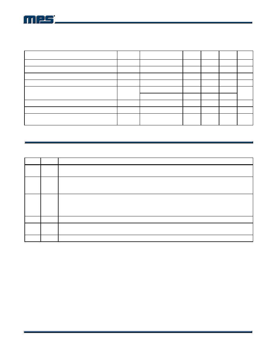
ELECTRICAL CHARACTERISTICS (continued)
VIN = 12V, TA = +25°C, unless otherwise noted.
Minimum On-Time (4)
tON
100
ns
Under Voltage Lockout Threshold Rising
2.5
2.8
3.1
V
Under Voltage Lockout Threshold Hysteresis
200
mV
EN Input Low Voltage
0.4
V
En Input High Voltage
1.2
V
VEN = 2V
2
EN Input Current
VEN = 0V
0.1
A
Supply Current (Shutdown)
VEN = 0V
0.1
A
Supply Current (Quiescent)
VEN = 2V, VFB = 1V
1.0
mA
Thermal Shutdown (4)
150
°C
Note:
4) Guaranteed by design.
PIN FUNCTIONS
Pin #
Name Description
1
BST
Bootstrap. This capacitor is needed to drive the power switch’s gate above the supply voltage. It
is connected between SW and BS pins to form a floating supply across the power switch driver.
2
GND
Ground. This pin is the voltage reference for the regulated output voltage. For this reason care
must be taken in its layout. This node should be placed outside of the D1 to C1 ground path to
prevent switching current spikes from inducing voltage noise into the part.
3
FB
Feedback. An external resistor divider from the output to GND, tapped to the FB pin sets the
output voltage. To prevent current limit run away during a short circuit fault condition the
frequency foldback comparator lowers the oscillator frequency when the FB voltage is below
250mV.
4
EN
On/Off Control Input. Pull above 1.2V to turn the device on.
5
IN
Supply Voltage. The MP2259 operates from a +4.5V to +16V unregulated input. C1 is needed
to prevent large voltage spikes from appearing at the input.
6
SW
Switch Output.
相关PDF资料 |
PDF描述 |
|---|---|
| MP2562DS-LF | SWITCHING REGULATOR, 4800 kHz SWITCHING FREQ-MAX, PDSO8 |
| MP258W | |
| MP254W | |
| MP2510W | |
| MP252W | |
相关代理商/技术参数 |
参数描述 |
|---|---|
| MP2259DT | 制造商:MPS 制造商全称:Monolithic Power Systems 功能描述:1A, 16V, 1.4MHz Step-Down Converter |
| MP2270 | 制造商:MPS 制造商全称:Monolithic Power Systems 功能描述:1.8A,24V,700kHz |
| MP2270DH | 制造商:MPS 制造商全称:Monolithic Power Systems 功能描述:1.8A, 24V, 700kHz Step-Down Converter |
| MP-229064-10-8A | 功能描述:打印机 MP-229064-10-8A RoHS:否 制造商:Seiko Instruments 产品:Printer 电源电压: 每行点数:9 x 320 打印速度:52.5 cps, 80 cps 纸张宽度:112 mm |
| MP-22C | 制造商:未知厂家 制造商全称:未知厂家 功能描述:SILICON PLANAR PHTODIODES |
发布紧急采购,3分钟左右您将得到回复。