- 您现在的位置:买卖IC网 > PDF目录296599 > MP2259DJ (MONOLITHIC POWER SYSTEMS INC) 1.8 A SWITCHING REGULATOR, 1400 kHz SWITCHING FREQ-MAX, PDSO6 PDF资料下载
参数资料
| 型号: | MP2259DJ |
| 厂商: | MONOLITHIC POWER SYSTEMS INC |
| 元件分类: | 稳压器 |
| 英文描述: | 1.8 A SWITCHING REGULATOR, 1400 kHz SWITCHING FREQ-MAX, PDSO6 |
| 封装: | MO-193AB, TSOT-23, 6 PIN |
| 文件页数: | 7/9页 |
| 文件大小: | 354K |
| 代理商: | MP2259DJ |
MP2259 – 1A, 16V, 1.4MHz STEP-DOWN CONVERTER
MP2259 Rev. 0.91
www.MonolithicPower.com
7
1/14/2008
MPS Proprietary Information. Unauthorized Photocopy and Duplication Prohibited.
2008 MPS. All Rights Reserved.
APPLICATION INFORMATION
Setting the Output Voltage
The external resistor divider is used to set the
output voltage (see the schematic on front
page). The feedback resistor R1 also sets the
feedback loop bandwidth with the internal
compensation capacitor (see Figure 1). R2 can
be determined by:
1
V
81
.
0
V
1
R
2
R
OUT
=
Table 1—Resistor Selection for Common
Output Voltages
VOUT (V)
R1 (k)
R2 (k)
1.8
80.6 (1%)
64.9 (1%)
2.5
49.9 (1%)
23.7 (1%)
3.3
49.9 (1%)
16.2 (1%)
5
49.9 (1%)
9.53 (1%)
Selecting the Inductor
A 1H to 10H inductor is recommended for
most applications. For highest efficiency, the
inductor’s DC resistance should be less than
200m. For most designs, the required
inductance value can be derived from the
following equation:
OSC
L
IN
OUT
IN
OUT
f
I
V
)
V
(
V
L
×
×
×
=
Where IL is the inductor ripple current.
Choose an inductor with a rating current higher
than the maximum load current. The maximum
inductor peak current can be calculated from:
2
I
L
LOAD
)
MAX
(
L
+
=
Under light load conditions below 100mA, a
larger inductance is recommended for improved
efficiency.
Selecting the Input Capacitor
The input capacitor (C1) reduces the surge
current drawn from the input and the switching
noise from the device. The input capacitor
impedance at the switching frequency should
be less than the input source impedance to
prevent high frequency switching current from
passing through the input. Ceramic capacitors
with X5R or X7R dielectrics are highly
recommended because of their low ESR and
small
temperature
coefficients.
For
most
applications, a 4.7F capacitor is sufficient.
Selecting the Output Capacitor
The output capacitor (C2) keeps output voltage
ripple small and ensures loop stability. The
output capacitor impedance should be low at
the switching frequency. Ceramic capacitors
with X5R or X7R dielectrics are recommended
for their low ESR characteristics. A 10F~ 22F
capacitor is good for most applications.
PC Board Layout
The high current paths (GND, IN and SW) should
be placed very close to the device with short,
direct and wide traces. The input capacitor needs
to be as close as possible to the IN and GND pins.
The external feedback resistors should be placed
next to the FB pin. Keep the switch node traces
short and away from the feedback network.
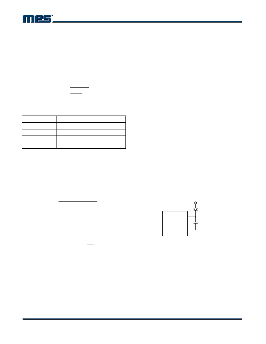
External Bootstrap Diode
It is recommended that an external bootstrap
diode be added when the input voltage is no
greater than 5V or 5V rail is available in the
system. This helps improve the efficiency of the
regulator. The bootstrap diode can be a low
cost one such as IN4148 or BAT54.
MP2259
SW
BS
10nF
5V (External) or
VIN (3.2V to 5V)
MP2259_F02
Figure 2—External Bootstrap Diode
This diode is also recommended for high duty
cycle operation (when
IN
OUT
V
>65%) and high
output voltage (VOUT>12V) applications.
相关PDF资料 |
PDF描述 |
|---|---|
| MP2562DS-LF | SWITCHING REGULATOR, 4800 kHz SWITCHING FREQ-MAX, PDSO8 |
| MP258W | |
| MP254W | |
| MP2510W | |
| MP252W | |
相关代理商/技术参数 |
参数描述 |
|---|---|
| MP2259DT | 制造商:MPS 制造商全称:Monolithic Power Systems 功能描述:1A, 16V, 1.4MHz Step-Down Converter |
| MP2270 | 制造商:MPS 制造商全称:Monolithic Power Systems 功能描述:1.8A,24V,700kHz |
| MP2270DH | 制造商:MPS 制造商全称:Monolithic Power Systems 功能描述:1.8A, 24V, 700kHz Step-Down Converter |
| MP-229064-10-8A | 功能描述:打印机 MP-229064-10-8A RoHS:否 制造商:Seiko Instruments 产品:Printer 电源电压: 每行点数:9 x 320 打印速度:52.5 cps, 80 cps 纸张宽度:112 mm |
| MP-22C | 制造商:未知厂家 制造商全称:未知厂家 功能描述:SILICON PLANAR PHTODIODES |
发布紧急采购,3分钟左右您将得到回复。