- 您现在的位置:买卖IC网 > PDF目录30997 > MR2510G (ON SEMICONDUCTOR) 25 A, 1000 V, SILICON, RECTIFIER DIODE PDF资料下载
参数资料
| 型号: | MR2510G |
| 厂商: | ON SEMICONDUCTOR |
| 元件分类: | 整流器 |
| 英文描述: | 25 A, 1000 V, SILICON, RECTIFIER DIODE |
| 封装: | PLASTIC, 2 PIN |
| 文件页数: | 6/7页 |
| 文件大小: | 125K |
| 代理商: | MR2510G |
MR2502, MR2504, MR2510
http://onsemi.com
376
ASSEMBLY AND SOLDERING INFORMATION
There are two basic areas of consideration for successful
implementation of button rectifiers:
1. Mounting and Handling
2. Soldering
each should be carefully examined before attempting a
finished assembly or mounting operation.
MOUNTING AND HANDLING
The button rectifier lends itself to a multitude of assembly
arrangements but one key consideration must always be
included:
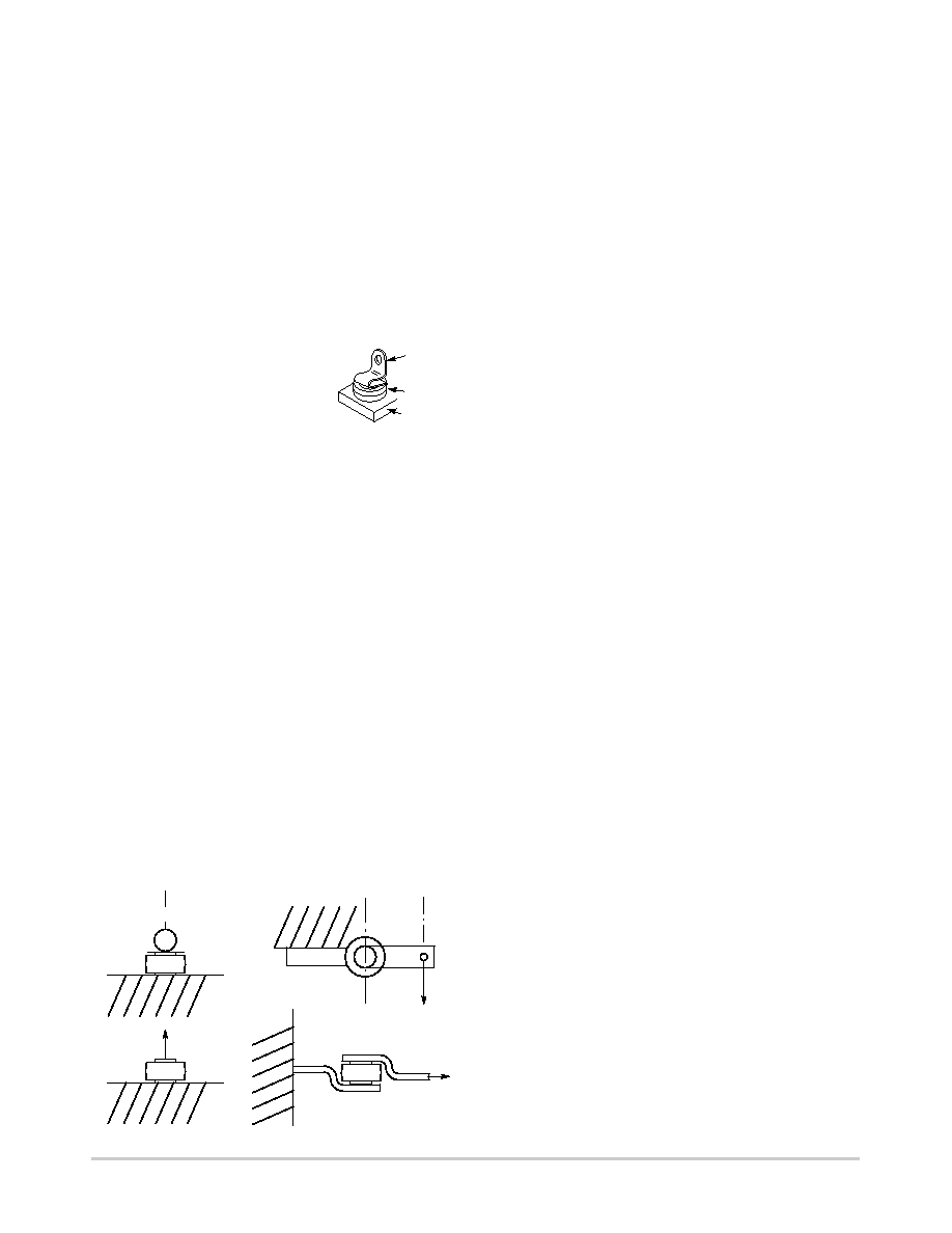
One Side of the Connections to
the Button Must Be Flexible!
This stress relief to the button should
also be chosen for maximum contact
area to afford the best heat transfer —
but not at the expense of flexibility.
For an annealed copper terminal a
thickness of 0.015
″ is suggested.
The base heat sink may be of various materials whose
shape and size are a function of the individual application
and the heat transfer requirements.
Common
Materials
Advantages and Disadvantages
Steel
Low Cost; relatively low heat conductivity
Copper
High Cost; high heat conductivity
Aluminum
Medium Cost; medium heat conductivity
Relatively expensive to plate and not all
platers can process aluminum.
Handling of the button during assembly must be relatively
gentle to minimize sharp impact shocks and avoid nicking
of the plastic. Improperly designed automatic handling
equipment is the worst source of unnecessary shocks.
Techniques for vacuum handling and spring loading should
be investigated.
The mechanical stress limits for the button diode are as
follows:
Compression
32 lbs.
142.3 Newton
Tension
32 lbs.
142.3 Newton
Torsion
6inch lbs.
0.68 Newtonmeters
Shear
55 lbs.
244.7 Newton
TENSION
COMPRESSION
TORSION
SHEAR
MECHANICAL STRESS
Exceeding these recommended maximums can result in
electrical degradation of the device.
SOLDERING
The button rectifier is basically a semiconductor chip
bonded between two nickelplated copper heat sinks with
an encapsulating material of thermalsetting silicone.
The exposed metal areas are also tin plated to enhance
solderability.
In the soldering process it is important that the
temperature not exceed 250
°C if device damage is to be
avoided. Various solder alloys can be used for this operation
but two types are recommended for best results:
1. 95% Sn, 5% Sb; melting point 237
°C
2. 96.5% tin, 3.5% silver; melting point 221
°C
3. 63% tin, 37% lead; melting point 183
°C
Solder is available as preforms or paste. The paste
contains both the metal and flux and can be dispensed
rapidly. The solder preform requires the application of a flux
to assure good wetting of the solder. The type of flux used
depends upon the degree of cleaning to be accomplished and
is a function of the metals involved. These fluxes range from
a mild rosin to a strong acid; e.g., Nickel plating oxides are
best removed by an acid base flux while an activated rosin
flux may be sufficient for tin plated parts.
Since the button is relatively lightweight, there is a
tendency for it to float when the solder becomes liquid. To
prevent bad joints and misalignment it is suggested that a
weighting or spring loaded fixture be employed. It is also
important that severe thermal shock (either heating or
cooling) be avoided as it may lead to damage of the die or
encapsulant of the part.
Button holding fixtures for use during soldering may be of
various materials. Stainless steel has a longer use life while
black anodized aluminum is less expensive and will limit heat
reflection and enhance absorption. The assembly volume will
influence the choice of materials. Fixture dimension
tolerances for locating the button must allow for expansion
during soldering as well as allowing for button clearance.
HEATING TECHNIQUES
The following four heating methods have their
advantages and disadvantages depending on volume of
buttons to be soldered.
1. Belt Furnaces readily handle large or small volumes
and are adaptable to establishment of “online’’
assembly since a variable belt speed sets the run rate.
Individual furnace zone controls make excellent
temperature control possible.
2. Flame Soldering involves the directing of natural gas
flame jets at the base of a heatsink as the heatsink is
indexed to various loadingheatingcoolingunloading
positions. This is the most economical labor method of
soldering large volumes. Flame soldering offers good
temperature
control
but
requires
sophisticated
temperature monitoring systems such as infrared.
Strain Relief Terminal
for Button Rectifier
Copper
Terminal
Button
Base
(Heat Sink Material)
相关PDF资料 |
PDF描述 |
|---|---|
| MR3025G | 25 A, 250 V, SILICON, RECTIFIER DIODE |
| MR850-G | 3 A, 50 V, SILICON, RECTIFIER DIODE, DO-201AD |
| MR851-G | 3 A, 100 V, SILICON, RECTIFIER DIODE, DO-201AD |
| MR852-G | 3 A, 200 V, SILICON, RECTIFIER DIODE, DO-201AD |
| MR856-G | 3 A, 600 V, SILICON, RECTIFIER DIODE, DO-201AD |
相关代理商/技术参数 |
参数描述 |
|---|---|
| MR2510L | 制造商:EIC 制造商全称:EIC discrete Semiconductors 功能描述:AUTOMOTIVE RECTIFIER DIODES |
| MR2512 | 制造商:EIC 制造商全称:EIC discrete Semiconductors 功能描述:AUTOMOTIVE RECTIFIER DIODES |
| MR2512L | 制造商:EIC 制造商全称:EIC discrete Semiconductors 功能描述:AUTOMOTIVE RECTIFIER DIODES |
发布紧急采购,3分钟左右您将得到回复。