- 您现在的位置:买卖IC网 > PDF目录45595 > MX10EXAQI (MACRONIX INTERNATIONAL CO LTD) 16-BIT, FLASH, 30 MHz, MICROCONTROLLER, PQCC44 PDF资料下载
参数资料
| 型号: | MX10EXAQI |
| 厂商: | MACRONIX INTERNATIONAL CO LTD |
| 元件分类: | 微控制器/微处理器 |
| 英文描述: | 16-BIT, FLASH, 30 MHz, MICROCONTROLLER, PQCC44 |
| 封装: | PLASTIC, LCC-44 |
| 文件页数: | 28/55页 |
| 文件大小: | 476K |
| 代理商: | MX10EXAQI |
第1页第2页第3页第4页第5页第6页第7页第8页第9页第10页第11页第12页第13页第14页第15页第16页第17页第18页第19页第20页第21页第22页第23页第24页第25页第26页第27页当前第28页第29页第30页第31页第32页第33页第34页第35页第36页第37页第38页第39页第40页第41页第42页第43页第44页第45页第46页第47页第48页第49页第50页第51页第52页第53页第54页第55页
34
P/N:PM0625 Specifications subject to change without notice, contact your sales representatives for the most update information. REV. 1.0, JUL. 01, 2005
MX10EXA
CLOCKING SCHEME/BAUD RATE GENERATION
The XA UARTS clock rates are determined by either a
fixed division (modes 0 and 2) of the oscillator clock or
by the Timer 1 or Timer 2 overflow rate (modes 1 and 3).
The clock for the UARTs in XA runs at 1 6x the Baud
rate. If the timers are used as the source for Baud Clock,
since maximum speed of timers/Baud Clock is Osc/4,
the maximum baud rate is timer overflow divided by 16
i.e. Osc/64.
In Mode 0, it is fixed at Osc/1 6. In Mode 2, however, the
fixed rate is Osc/32.
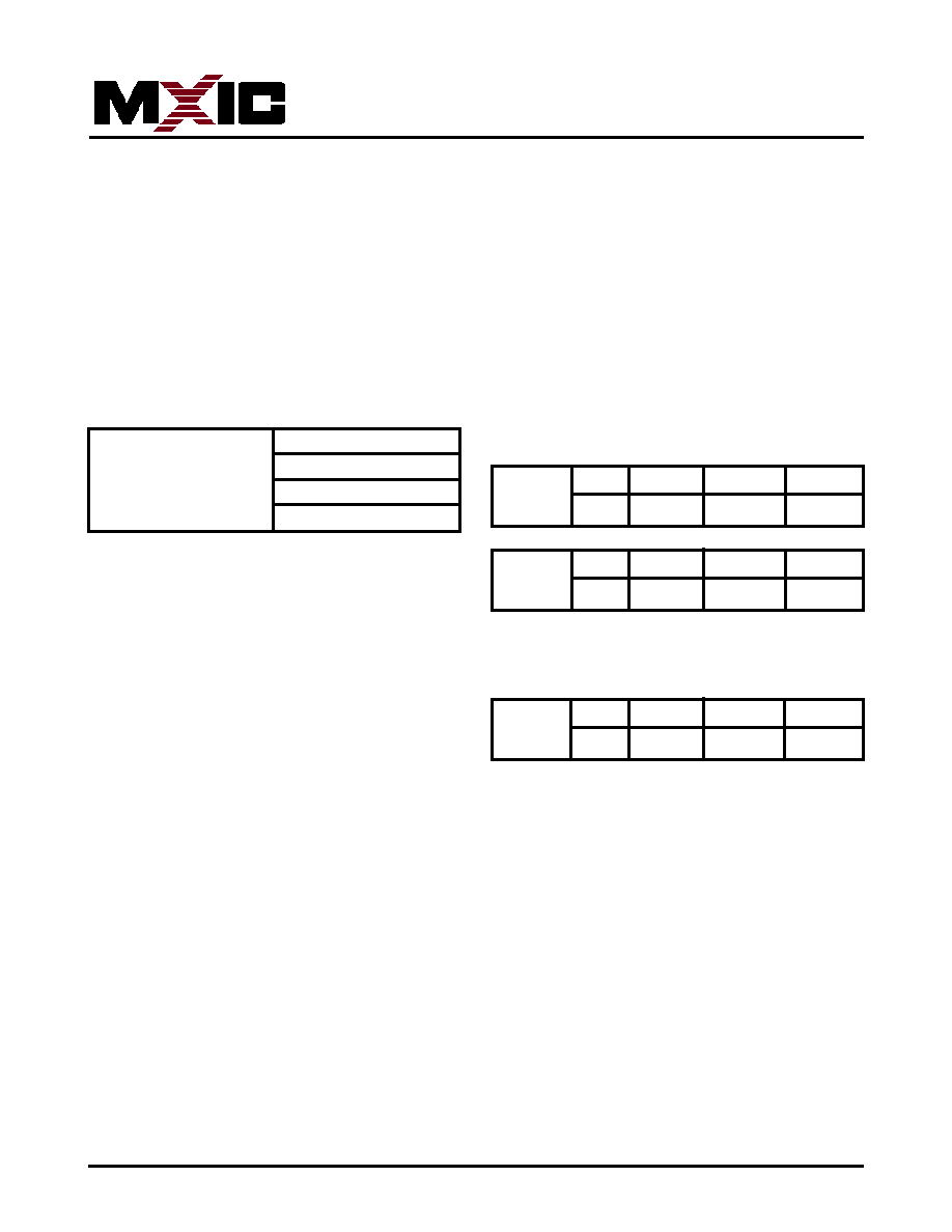
Pre-scaler
00
Osc/4
for all Timers T0, 1, 2,
01
Osc/16
controlled by PT1, PT0
10
Osc/64
bits in SCR
11
reserved
Baud Rate for UART Mode 0:
Baud_Rate = Osc/16
Baud Rate calculation for UART Mode 1 and 3:
Baud_Rate
= Timer_Rate/16
Timer_Rate
=Osc/(N*(Timer_Range-
Timer_Reload_Value))
where N = the TCLK prescaler value: 4,16, or 64.
and Timer_Range = 256 for timer 1 in mode 2.
65536 for timer 1 in mode 0 and timer 2 in count up
mode.
The timer reload value may be calculated as follows:
Timer_Reload_Value
=
Timer_Range(Osc/
(Baud_Rate*N*1 6))
NOTES:
1.The maximum baud rate for a UART in mode 1 or 3 is
Osc/64.
2.The lowest possible baud rate (for a given oscillator
frequency and N value) may be found by using a timer
reload value of 0.
3.The timer reload value may never be larger than the
timer range.
4.If a timer reload value calculation gives a negative or
fractional result, the baud rate requested is not pos-
sible at the given oscillator frequency and N value.
Baud Rate for UART Mode 2:
Baud_Rate = Osc/32
Using Timer 2 to Generate Baud Rates
Timer T2 is a 16-bit up/down counter in XA. As a baud
rate generator, timer 2 is selected as a clock source for
either/both UART0 and UART1 transmitters and/or re-
ceivers by setting TCLKn and/or RCLKn in T2CON and
T2MOD. As the baud rate generator, T2 is incremented
as Osc/N where N = 4, 16 or 64 depending on TCLK as
programmed in the SCR bits PT1, and PTO. So, if T2 is
the source of one UART, the other UART could be clocked
by either T1 overflow or fixed clock, and the UARTs could
run independently with different baud rates.
T2CON
bit5
bit4
0x418
RCLK0
TCLK0
T2MOD
bit5
bit4
0x419
RCLK1
TCLK1
SCR
bit3
bit2
0x440
PT1
PT0
Prescaler Select for Timer Clock (TCLK)
相关PDF资料 |
PDF描述 |
|---|---|
| MX10EXAUI | 16-BIT, FLASH, 30 MHz, MICROCONTROLLER, PQFP44 |
| MX836818 | 1 TIMER(S), REAL TIME CLOCK, PDIP24 |
| MZ4617RL2 | 2.4 V, 0.5 W, SILICON, UNIDIRECTIONAL VOLTAGE REGULATOR DIODE, DO-204AH |
| MZ4616RL2 | 2.2 V, 0.5 W, SILICON, UNIDIRECTIONAL VOLTAGE REGULATOR DIODE, DO-204AH |
| MZ4625TA2 | 5.1 V, 0.5 W, SILICON, UNIDIRECTIONAL VOLTAGE REGULATOR DIODE, DO-204AH |
相关代理商/技术参数 |
参数描述 |
|---|---|
| MX10EXAUC | 制造商:MCNIX 制造商全称:Macronix International 功能描述:XA 16-bit Microcontroller Family 64K Flash/2K RAM, Watchdog, 2UARTs |
| MX10EXAUCG | 制造商:MCNIX 制造商全称:Macronix International 功能描述:XA 16-bit Microcontroller Family 64K Flash/2K RAM, Watchdog, 2UARTs |
| MX10F201FC | 制造商:MCNIX 制造商全称:Macronix International 功能描述:High-Performance and Low Power Microcontroller designed for Use Many Applications |
| MX10FMAXDPC | 制造商:MCNIX 制造商全称:Macronix International 功能描述:SINGLE-CHIP 8-BIT MICROCONTROLLER |
| MX10FMAXDQC | 制造商:MCNIX 制造商全称:Macronix International 功能描述:SINGLE-CHIP 8-BIT MICROCONTROLLER |
发布紧急采购,3分钟左右您将得到回复。