- 您现在的位置:买卖IC网 > PDF目录19365 > IR2521DSTRPBF (International Rectifier)IC BALLAST CTLR ADAPTIVE 8-SOIC PDF资料下载
参数资料
| 型号: | IR2521DSTRPBF |
| 厂商: | International Rectifier |
| 文件页数: | 10/17页 |
| 文件大小: | 0K |
| 描述: | IC BALLAST CTLR ADAPTIVE 8-SOIC |
| 标准包装: | 1 |
| 封装/外壳: | 8-SOIC(0.154",3.90mm 宽) |
| 供应商设备封装: | 8-SOIC |
| 包装: | 标准包装 |
| 其它名称: | IR2521DSTRPBFDKR |
�� �
�
�IR2520D(S)&� (PbF)�
�over-current� fault.� By� using� the� RDSon� of� the� external� low-�
�side� MOSFET� for� current� sensing� and� the� VS-sensing�
�circuitry,� the� IR2520D� eliminates� the� need� for� an� additional�
�current� sensing� resistor,� filter� and� current-sensing� pin.� To�
�cancel� changes� in� the� RDSon� value� due� to� temperature� and�
�MOSFET� variations,� the� IR2520D� performs� a� crest� factor�
�measurement� that� detects� when� the� peak� current� exceeds�
�the� average� current� by� a� factor� of� 5� (CSCF).� Measuring� the�
�crest� factor� is� ideal� for� detecting� when� the� inductor� saturates�
�due� to� excessive� current� that� occurs� in� the� resonant� tank�
�when� the� frequency� sweeps� through� resonance� and� the�
�lamp� does� not� ignite.� When� the� VCO� voltage� ramps� up� for�
�the� first� time� from� zero,� the� resonant� tank� current� and�
�voltages� increase� as� the� frequency� decreases� towards�
�resonance� (Figure� 8).� If� the� lamp� does� not� ignite,� the� inductor�
�current� will� eventually� saturate� but� the� crest� factor� fault�
�protection� is� not� active� until� the� VCO� voltage� exceeds� 4.8V�
�(V� VCO_RUN� )� for� the� first� time.� The� frequency� will� continue�
�decreasing� to� the� capacitive� side� of� resonance� towards�
�the� minimum� frequency� setting� and� the� resonant� tank� current�
�and� voltages� will� decrease� again.� When� the� VCO� voltage�
�exceeds� 4.8V� (V� VCO_RUN� ),� the� IC� enters� Run� Mode� and�
�the� non-ZVS� protection� and� crest� factor� protection� are� both�
�faults.� This� can� occur� when� a� half-bridge� MOSFET� is�
�selected� that� has� an� RDSon� that� is� too� large� for� the� application�
�causing� the� internal� average� to� exceed� the� maximum� limit.�
�FAULT� MODE�
�During� Run� Mode,� should� the� VCO� voltage� decrease� below�
�0.82V� (V� VCOSD� )� or� a� crest� factor� fault� occur,� the� IR2520D�
�will� enter� Fault� Mode� (see� State� Diagram).� The� LO� and� HO�
�gate� driver� outputs� are� both� latched� ‘low’� so� that� the� half-�
�bridge� is� disabled.� The� VCO� pin� is� pulled� low� to� COM� and�
�the� FMIN� pin� decreases� from� 5V� to� COM.� VCC� draws�
�micro-power� current� (I� CCFLT� )� so� that� VCC� stays� at� the�
�clamp� voltage� and� the� IC� remains� in� Fault� Mode� without� the�
�need� for� the� charge-pump� auxiliary� supply.� To� exit� Fault�
�Mode� and� return� to� Frequency� Sweep� Mode,� VCC� must� be�
�cycled� below� the� UVLO-� threshold� and� back� above� the�
�UVLO+� threshold.�
�LO�
�enabled.� The� non-ZVS� protection� will� increase� the�
�frequency� again� cycle-by-cycle� towards� resonance� from�
�the� capacitive� side.� The� resonant� tank� current� will� increase�
�again� as� the� frequency� nears� resonance� until� the� inductor�
�saturates� again.�
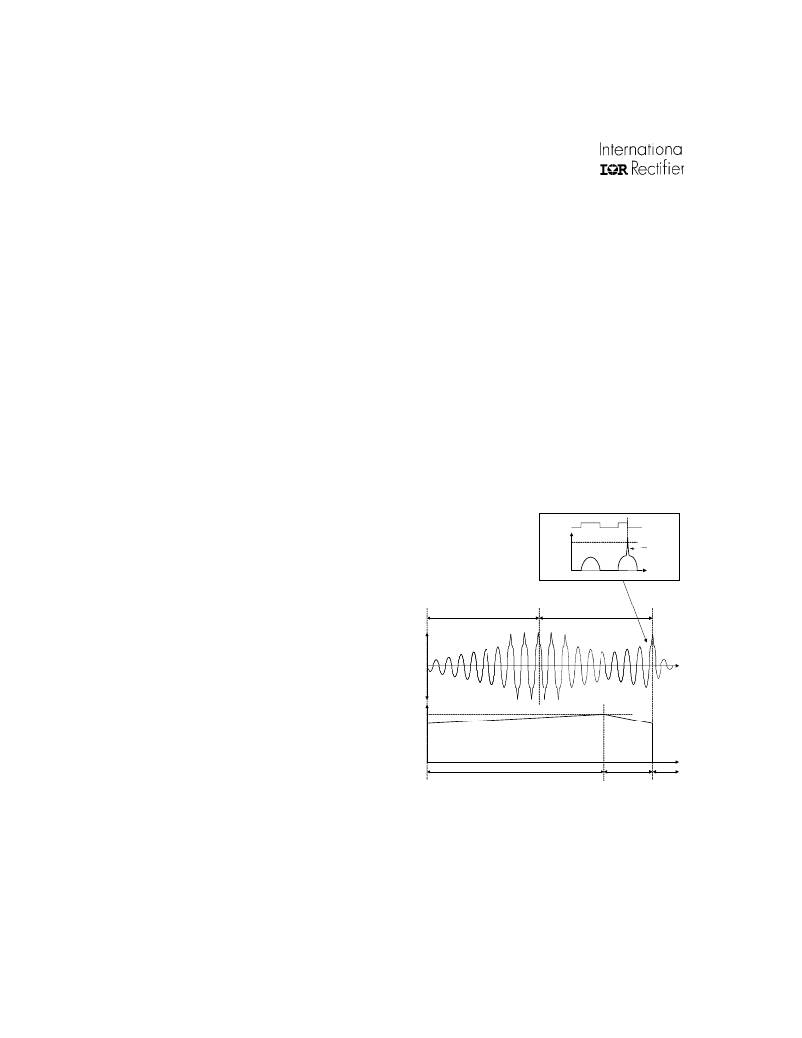
�INDUCTIVE� SIDE�
�AVG*5�
�IMLS�
�CAPACITIVE� SIDE�
�Inductor�
�saturation�
�The� crest� factor� protection� is� now� enabled� and� measures�
�the� instantaneous� voltage� at� the� VS� pin� only� during� the� time�
�when� LO� is� ‘high’� and� after� an� initial� 1us� blank� time� from� the�
�rising� edge� of� LO.� The� blank� time� is� necessary� to� prevent�
�the� crest� factor� protection� circuit� from� reacting� to� a� non-�
�ZVS� condition.� An� internal� averaging� circuit� averages� the�
�instantaneous� voltage� at� the� VS� pin� over� 10� to� 20� switching�
�cycles� of� LO.� During� Run� Mode,� the� first� time� the� inductor�
�saturates� when� LO� is� ‘high’� (after� the� 1us� blank� time)� and�
�the� peak� current� exceeds� the� average� by� 5� (CSCF),� the�
�IR2520D� will� enter� Fault� Mode� and� both� LO� and� HO� outputs�
�will� be� latched� ‘low’.� The� half-bridge� will� be� safely� disabled�
�IL�
�4.6V�
�VVCO�
�OF� RESONANCE�
�OF� RESONANCE�
�before� any� damage� can� occur� to� the� ballast� components.�
�FREQUENCY� SWEEP� MODE�
�RUN� MODE�
�FAULT� MODE�
�The� crest� factor� peak-to-average� fault� factor� varies� as� a�
�function� of� the� internal� average� (Figure� 20).� The� maximum�
�internal� average� should� be� below� 3.0� volts.� Should� the�
�average� exceed� this� amount,� the� multiplied� average� voltage�
�can� exceed� the� maximum� limit� of� the� VS� sensing� circuit� and�
�the� VS� sensing� circuit� will� no� longer� detect� crest� factor�
�10�
�Fig.� 8� Crest� factor� protection� timing� diagram�
�www.irf.com�
�相关PDF资料 |
PDF描述 |
|---|---|
| S392K59Y5PP63K7R | CAP CER 3900PF 2KV 10% RADIAL |
| 5-787355-1 | CONN RCPT 9POS VERT SOLDER CUP |
| ECC08DRTF-S13 | CONN EDGECARD 16POS .100 EXTEND |
| 1N5406RLG | DIODE STD REC 3A 600V DO201AD |
| S332K53Y5PP63K7R | CAP CER 3300PF 2KV 10% RADIAL |
相关代理商/技术参数 |
参数描述 |
|---|---|
| NB6L295MNG | 功能描述:延迟线/计时元素 LVPECL DUAL PRG DLAY RoHS:否 制造商:Micrel 功能:Active Programmable Delay Line 传播延迟时间:1000 ps 工作温度范围: 封装 / 箱体:QFN-24 封装:Tube |
| NB6L295MNGEVB | 功能描述:电源管理IC开发工具 NB6L295 EVAL BOARD RoHS:否 制造商:Maxim Integrated 产品:Evaluation Kits 类型:Battery Management 工具用于评估:MAX17710GB 输入电压: 输出电压:1.8 V |
| NB6L295MNTXG | 功能描述:延迟线/计时元素 LVPECL DUAL PRG DLAY RoHS:否 制造商:Micrel 功能:Active Programmable Delay Line 传播延迟时间:1000 ps 工作温度范围: 封装 / 箱体:QFN-24 封装:Tube |
| NB6L56MNG | 功能描述:时钟缓冲器 TSMC 2.5V/3.3V DUAL DIFF RoHS:否 制造商:Texas Instruments 输出端数量:5 最大输入频率:40 MHz 传播延迟(最大值): 电源电压-最大:3.45 V 电源电压-最小:2.375 V 最大功率耗散: 最大工作温度:+ 85 C 最小工作温度:- 40 C 封装 / 箱体:LLP-24 封装:Reel |
| NB6L56MNTXG | 功能描述:时钟缓冲器 2.5V/3.3V DUAL DIFFERENTI RoHS:否 制造商:Texas Instruments 输出端数量:5 最大输入频率:40 MHz 传播延迟(最大值): 电源电压-最大:3.45 V 电源电压-最小:2.375 V 最大功率耗散: 最大工作温度:+ 85 C 最小工作温度:- 40 C 封装 / 箱体:LLP-24 封装:Reel |
发布紧急采购,3分钟左右您将得到回复。