- 您现在的位置:买卖IC网 > PDF目录22150 > NCP1351BDR2G (ON Semiconductor)IC CTLR PWM VAR-OFF TIME 8-SOIC PDF资料下载
参数资料
| 型号: | NCP1351BDR2G |
| 厂商: | ON Semiconductor |
| 文件页数: | 15/27页 |
| 文件大小: | 0K |
| 描述: | IC CTLR PWM VAR-OFF TIME 8-SOIC |
| 标准包装: | 1 |
| 输出隔离: | 隔离 |
| 频率范围: | 调节 |
| 输入电压: | 9.5 V ~ 28 V |
| 工作温度: | -25°C ~ 125°C |
| 封装/外壳: | 8-SOIC(0.154",3.90mm 宽) |
| 供应商设备封装: | 8-SOICN |
| 包装: | 标准包装 |
| 其它名称: | NCP1351BDR2GOSDKR |
第1页第2页第3页第4页第5页第6页第7页第8页第9页第10页第11页第12页第13页第14页当前第15页第16页第17页第18页第19页第20页第21页第22页第23页第24页第25页第26页第27页
�� �
�
�NCP1351�
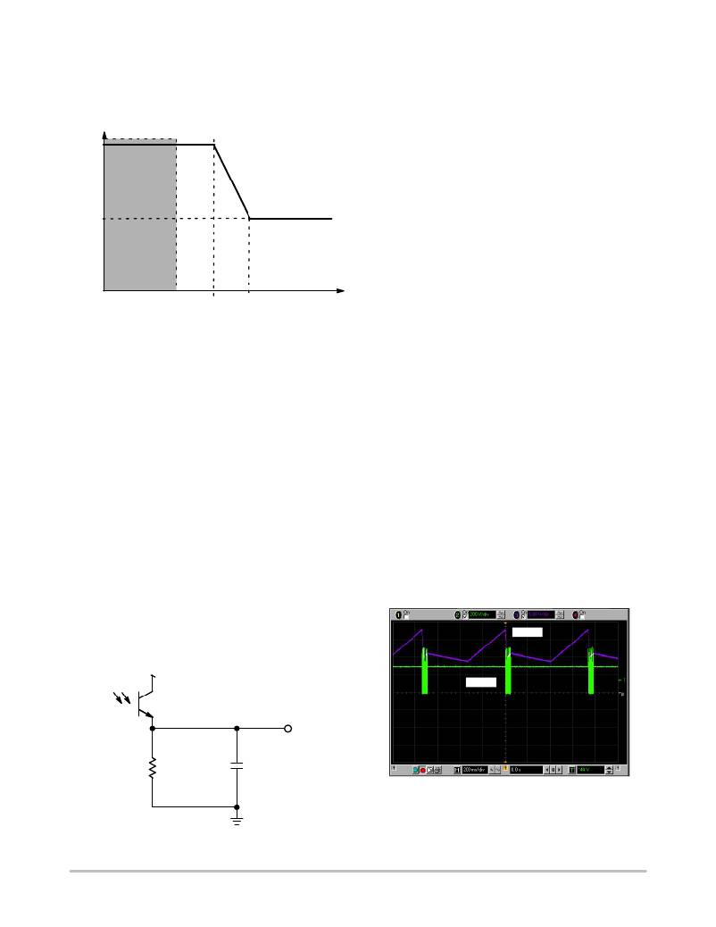
�At� this� point,� the� current� is� fully� compressed� and� remains�
�frozen.� To� further� decrease� the� transmitted� power,� the�
�frequency� does� not� have� other� choice� than� going� down.�
�CS� Current�
�270� m� A�
�FAULT�
�Fault� detection�
�The� fault� detection� circuitry� permanently� observes� the� FB�
�current,� as� shown� on� Figure� 19.� When� the� feedback� current�
�decreases� below� 40� m� A,� an� external� capacitor� is� charged� by�
�a� 11.7� m� A� source.� As� the� voltage� rises,� a� comparator� detects�
�when� it� reaches� 5� V� typical.� Upon� detection,� there� can� be�
�two� different� scenarios:�
�1.� A� version:� the� circuit� immediately� latches-off� and�
�remains� latched� until� the� voltage� on� the� current�
�into� the� V� CC� pin� drops� below� a� few� m� A.� The� latch�
�70� m� A�
�(A,� B� versions)�
�is� made� via� an� internal� SCR� circuit� who� holds�
�VCC� to� around� 6� V� when� fired.� As� long� as� the�
�current� flowing� through� this� latch� is� above� a� few�
�m� A,� the� circuit� remains� locked-out.� When� the� user�
�unplugs� the� converter,� the� V� CC� current� falls� down�
�and� resets� the� latch.�
�40� m� A� 60� m� A� 80� m� A� FB� Current�
�Figure� 16.� The� NCP1351� Peak� Current� Compression�
�Scheme�
�Looking� to� the� data-sheet� specifications,� the� maximum�
�peak� current� is� set� to� 270� m� A� whereas� the� compressed�
�current� goes� down� to� 70� m� A.� The� NCP1351� can� thus� be�
�considered� as� a� multi� operating� mode� circuit:�
�?� Real� fixed� peak� current� /� variable� frequency� mode� for�
�FB� current� below� 60� m� A.�
�?� Then� maximum� peak� current� decreases� to� I� CS,min� over� a�
�narrow� linear� range� of� I� FB� (to� avoid� instability� created�
�by� a� discrete� jump� from� I� CS,max� to� I� CS,min� ),� between�
�60� m� A� and� 80� m� A.�
�?� Then� if� I� FB� keeps� on� increasing,� in� a� real� fixed� peak�
�current/variable� frequency� mode� with� reduced� peak�
�current�
�For� biasing� purposes� and� noise� immunity� improvements,�
�we� recommend� to� wire� a� pulldown� resistor� and� a� capacitor�
�in� parallel� from� the� FB� pin� to� the� controller� ground�
�(Figure� 17).� Please� keep� these� elements� as� close� as� possible�
�to� the� circuit.� The� pulldown� resistor� increases� the�
�optocoupler� current� but� also� plays� a� role� in� standby.� We�
�found� that� a� 2.5� k� W� resistor� was� giving� a� good� tradeoff�
�between� optocoupler� operating� current� (internal� pole�
�2.� B� version:� the� circuit� stops� its� output� pulses� and�
�the� auxiliary� V� CC� decreases� via� the� controller� own�
�consumption� (� ≈� 600� m� A).� When� it� touches� the�
�V� CC(min)� point,� the� circuit� re-starts� and� attempts� to�
�crank� the� power� supply.� If� it� fails� again,� an� hiccup�
�mode� takes� place� (Figure� 18).�
�3.� C� version:� this� version� includes� the� dual� Over�
�Current� Protection� (OCP)� level.� When� the�
�switching� frequency� imposed� by� the� feedback� loop�
�reaches� around� 50%� of� the� maximum� value� set� by�
�the� Ct� capacitor,� the� timer� starts� to� count� down.� If�
�the� fault� disappears,� the� timer� is� reset.� When� the�
�fault� is� finally� confirmed,� the� controller� latches� off�
�as� the� A� version.�
�4.� D� version:� this� version� includes� the� dual� Over�
�Current� Protection� (OCP)� level.� When� the�
�switching� frequency� imposed� by� the� feedback� loop�
�reaches� around� 50%� of� the� maximum� value� set� by�
�the� Ct� capacitor,� the� timer� starts� to� count� down.� If�
�the� fault� disappears,� the� timer� is� reset.� When� the�
�fault� is� finally� confirmed,� the� controller� enters�
�auto-recovery� mode,� as� with� the� B� version.�
�V� CC�
�position)� and� standby� power.�
�V� CC�
�V� drv�
�FB�
�R1�
�2.5k�
�C1�
�100nF�
�Figure� 18.� Hiccup� Occurs� with� the� B� Version� Only,�
�the� A� Version� Being� Latched�
�Figure� 17.� The� Recommended� Feedback�
�Arrangement� Around� the� FB� Pin�
�The� duty-burst� in� fault� is� around� 7%� in� this� particular�
�case.�
�http://onsemi.com�
�15�
�相关PDF资料 |
PDF描述 |
|---|---|
| VI-JW3-CW-B1 | CONVERTER MOD DC/DC 24V 100W |
| AMC15DRAI | CONN EDGECARD 30POS .100 R/A DIP |
| RCM06DRMI-S288 | CONN EDGECARD 12POS .156 EXTEND |
| ACB50DHLT | CONN EDGECARD 100PS .050 DIP SLD |
| VI-J1M-CW-B1 | CONVERTER MOD DC/DC 10V 100W |
相关代理商/技术参数 |
参数描述 |
|---|---|
| NCP1351BPG | 功能描述:电流型 PWM 控制器 VRIABLE OFF TM CNTRL RoHS:否 制造商:Texas Instruments 开关频率:27 KHz 上升时间: 下降时间: 工作电源电压:6 V to 15 V 工作电源电流:1.5 mA 输出端数量:1 最大工作温度:+ 105 C 安装风格:SMD/SMT 封装 / 箱体:TSSOP-14 |
| NCP1351CDR2G | 功能描述:电流型 PWM 控制器 PWM CONTROLLER RoHS:否 制造商:Texas Instruments 开关频率:27 KHz 上升时间: 下降时间: 工作电源电压:6 V to 15 V 工作电源电流:1.5 mA 输出端数量:1 最大工作温度:+ 105 C 安装风格:SMD/SMT 封装 / 箱体:TSSOP-14 |
| NCP1351CPG | 功能描述:电流型 PWM 控制器 VRIABLE OFF TM CNTRL RoHS:否 制造商:Texas Instruments 开关频率:27 KHz 上升时间: 下降时间: 工作电源电压:6 V to 15 V 工作电源电流:1.5 mA 输出端数量:1 最大工作温度:+ 105 C 安装风格:SMD/SMT 封装 / 箱体:TSSOP-14 |
| NCP1351DDR2G | 功能描述:电流型 PWM 控制器 PWM CONTROLLER RoHS:否 制造商:Texas Instruments 开关频率:27 KHz 上升时间: 下降时间: 工作电源电压:6 V to 15 V 工作电源电流:1.5 mA 输出端数量:1 最大工作温度:+ 105 C 安装风格:SMD/SMT 封装 / 箱体:TSSOP-14 |
| NCP1351DPG | 功能描述:电流型 PWM 控制器 VRIABLE OFF TM CNTRL RoHS:否 制造商:Texas Instruments 开关频率:27 KHz 上升时间: 下降时间: 工作电源电压:6 V to 15 V 工作电源电流:1.5 mA 输出端数量:1 最大工作温度:+ 105 C 安装风格:SMD/SMT 封装 / 箱体:TSSOP-14 |
发布紧急采购,3分钟左右您将得到回复。