- 您现在的位置:买卖IC网 > PDF目录19516 > NCP1382DR2G (ON Semiconductor)IC CTRLR PWM OVP OTP 14SOIC PDF资料下载
参数资料
| 型号: | NCP1382DR2G |
| 厂商: | ON Semiconductor |
| 文件页数: | 7/25页 |
| 文件大小: | 0K |
| 描述: | IC CTRLR PWM OVP OTP 14SOIC |
| 标准包装: | 2,500 |
| 输出隔离: | 隔离 |
| 频率范围: | 调节 |
| 输入电压: | 9 V ~ 20 V |
| 工作温度: | 0°C ~ 125°C |
| 封装/外壳: | 14-SOIC(0.154",3.90mm 宽) |
| 供应商设备封装: | 14-SOICN |
| 包装: | 带卷 (TR) |
�� �
�
�NCP1381,� NCP1382�
�Startup� sequence�
�When� the� power� supply� is� first� connected� to� the� mains�
�outlet,� the� NCP1381/82� starts� to� consume� current.� However,�
�due� to� a� novel� architecture,� the� internal� startup� current� is�
�kept� very� low,� below� 15� m� A� as� a� maximum� value.� The�
�current� delivered� by� the� startup� resistor� also� feeds� the� V� CC�
�capacitor� and� its� voltage� rises.� When� the� voltage� on� this�
�capacitor� reaches� the� VCC� ON� level� (typically� 15� V),� the�
�controller� delivers� pulses� and� increases� its� consumption.� At�
�this� time,� the� V� CC� capacitor� alone� supplies� the� controller:� the�
�auxiliary� supply� is� supposed� to� take� over� before� V� CC�
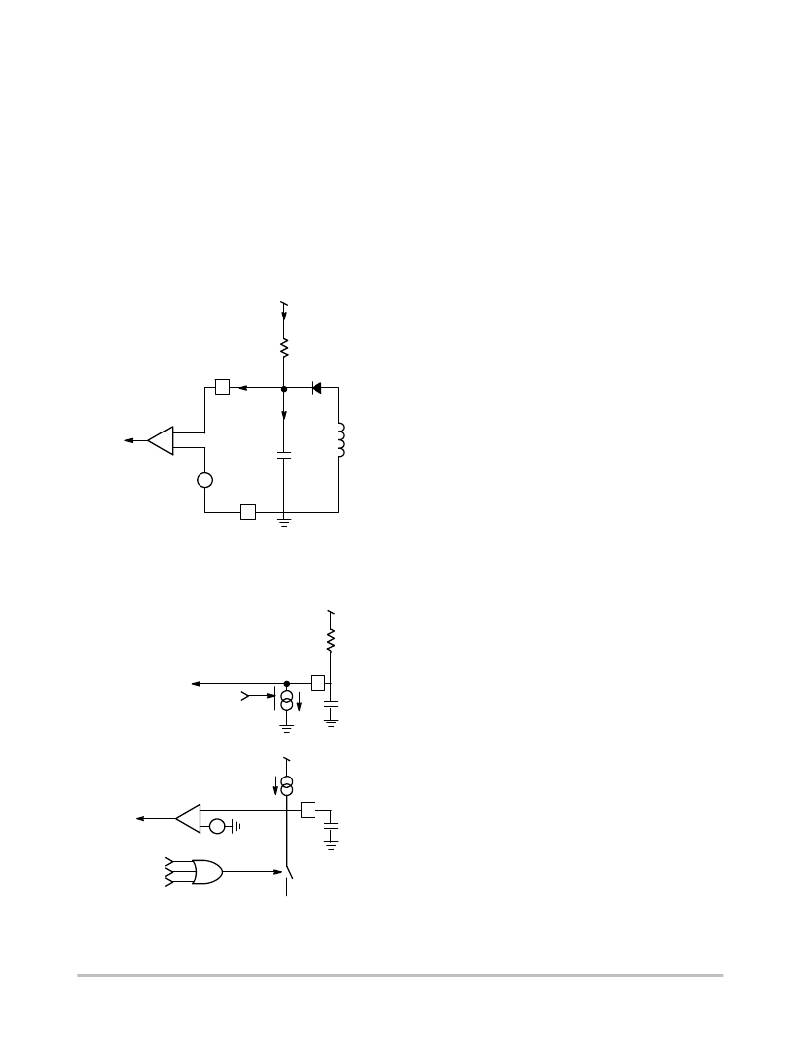
�collapses� below� VCC� OFF� .� Figure� 3� shows� the� internal�
�arrangement� of� this� structure:�
�High� Voltage�
�I� total�
�As� soon� as� V� CC� reaches� 15� V� (VCC� ON� ),� driving� pulses� are�
�delivered� on� Pin� 9� and� the� auxiliary� winding� grows� up� the�
�V� CC� pin.� Because� the� output� voltage� is� below� the� target� (the�
�SMPS� is� starting� up),� the� controller� smoothly� pushes� the�
�peak� current� to� I� max� (0.8� V� /� R� sense� )� which� is� reached� after�
�5� ms� (typical� internal� soft--start� period).� After� soft--start�
�completion,� the� peak� current� setpoint� reaches� its� maximum�
�(during� the� startup� period� but� also� anytime� a� short--circuit�
�occurs),� an� internal� error� flag� is� asserted,� I� P� Flag,� testifying�
�that� the� system� is� pushed� to� the� maximum� power� (I� P� =� I� P�
�maximum).� This� flag� is� used� to� detect� a� faulty� condition,�
�where� the� converter� asks� for� the� maximum� peak� capability�
�longer� than� what� has� been� programmed� by� the� designer.� The�
�duration� of� the� faulty� condition� is� actually� set� up� by� a�
�capacitor� connected� to� Pin� 4.�
�Figure� 4� shows� a� portion� of� this� internal� arrangement.� If�
�the� fault� comparator� acknowledges� for� a� problem,� the�
�10�
�I� startup�
�R� startup�
�controller� stops� all� driving� pulses� and� turns--on� the� internal�
�I� CC3� current--source.� This� source� serves� for� the� latch--off�
�phase� creation,� that� is� to� say,� forcing� the� V� CC� to� go� down,�
�despite� the� presence� of� the� startup� current� still� flowing� via�
�Winding�
�UVLO�
�+�
�--�
�+�
�VCC� ON�
�VCC� OFF�
�Auxiliary�
�+�
�CV� CC�
�the� startup� resistor.� Therefore,� I� CC3� should� be� greater� than�
�I� total� to� ensure� proper� operation.� When� V� CC� reaches� a� level�
�of� 7� V,� I� CC3� turns� to� zero� and� the� startup� current� can� lift� V� CC�
�up� again.� When� V� CC� reaches� 15� V,� a� new� attempt� is� made.�
�If� the� fault� is� still� there,� pulses� last� either� the� timer� duration�
�or� are� prematurely� stopped� if� a� VCC� OFF� condition� occurs�
�sooner,� and� a� new� latchoff� phase� takes� place.� If� the� fault� has�
�8�
�Figure� 3.� The� Startup� Resistor� Brings� V� CC�
�Above� 15� V�
�gone,� the� converter� resumes� operation.� Figure� 5� portrays� the�
�waveforms� obtained� during� a� startup� sequence� followed� by�
�a� fault.� One� can� see� the� action� of� the� I� CC3� source� which�
�creates� the� latchoff� phase� and� the� various� resets� events� on� the�
�timer� capacitor� in� presence� of� the� soft--start� end� or� an� aborted�
�HV�
�R� startup�
�fault� sequence.�
�Knowing� that� I� timer� equals� 10� m� A,� we� can� calculate� the�
�capacitor� needed� to� reach� 4� V� in� a� typical� time� period.�
�Suppose� we� would� like� a� 100� ms� fault� duration,� therefore:�
�V� CC�
�Management�
�Latchoff�
�V� CC�
�10�
�I� CC3�
�+�
�CV� CC�
�C� timer� =� 10� m� x� 100� m� /� 4� =� 250� nF,� select� a� 0.22� m� F.�
�V� DD�
�I� timer�
�Fault�
�Confirmed�
�+�
�--�
�+�
�4�
�C� timer�
�4.0� V�
�Soft--Start�
�Soft--Burst�
�I� P� Flag�
�Reset�
�SW�
�Figure� 4.� The� Timer� Section� Uses� a� Current� Source�
�to� Charge� Up� the� Capacitor�
�http://onsemi.com�
�7�
�相关PDF资料 |
PDF描述 |
|---|---|
| VI-B0N-CY-F3 | CONVERTER MOD DC/DC 18.5V 50W |
| R15P215S/X2/P/R6.4 | CONV DC/DC 2W 15VIN 15VOUT |
| V24A12E400B3 | CONVERTER MOD DC/DC 12V 400W |
| RCB105DHNT | CONN EDGECARD 210PS DIP .050 SLD |
| TPSR475M010R3000 | CAP TANT 4.7UF 10V 20% 0805 |
相关代理商/技术参数 |
参数描述 |
|---|---|
| NCP1392B | 制造商:ONSEMI 制造商全称:ON Semiconductor 功能描述:High-Voltage Half-Bridge Driver with Inbuilt Oscillator |
| NCP1392B_09 | 制造商:ONSEMI 制造商全称:ON Semiconductor 功能描述:High-Voltage Half-Bridge Driver with Inbuiltc Oscillator |
| NCP1392BDR2G | 功能描述:功率驱动器IC HV HALF-BRIDGE DRVER RoHS:否 制造商:Micrel 产品:MOSFET Gate Drivers 类型:Low Cost High or Low Side MOSFET Driver 上升时间: 下降时间: 电源电压-最大:30 V 电源电压-最小:2.75 V 电源电流: 最大功率耗散: 最大工作温度:+ 85 C 安装风格:SMD/SMT 封装 / 箱体:SOIC-8 封装:Tube |
| NCP1392DDR2G | 功能描述:功率驱动器IC HV HALF-BRIDGE DRIVER RoHS:否 制造商:Micrel 产品:MOSFET Gate Drivers 类型:Low Cost High or Low Side MOSFET Driver 上升时间: 下降时间: 电源电压-最大:30 V 电源电压-最小:2.75 V 电源电流: 最大功率耗散: 最大工作温度:+ 85 C 安装风格:SMD/SMT 封装 / 箱体:SOIC-8 封装:Tube |
| NCP1392LCDTVGEVB | 功能描述:BOARD EVAL NCP1392HV RoHS:是 类别:编程器,开发系统 >> 评估板 - DC/DC 与 AC/DC(离线)SMPS 系列:* 产品培训模块:Obsolescence Mitigation Program 标准包装:1 系列:True Shutdown™ 主要目的:DC/DC,步升 输出及类型:1,非隔离 功率 - 输出:- 输出电压:- 电流 - 输出:1A 输入电压:2.5 V ~ 5.5 V 稳压器拓扑结构:升压 频率 - 开关:3MHz 板类型:完全填充 已供物品:板 已用 IC / 零件:MAX8969 |
发布紧急采购,3分钟左右您将得到回复。