- 您现在的位置:买卖IC网 > Datasheet目录45 > NCP1927DR2G (ON Semiconductor)IC CTLR PFC/FLYBACK 16-SOIC Datasheet资料下载
参数资料
| 型号: | NCP1927DR2G |
| 厂商: | ON Semiconductor |
| 文件页数: | 14/24页 |
| 文件大小: | 531K |
| 描述: | IC CTLR PFC/FLYBACK 16-SOIC |
| 标准包装: | 2,500 |
| 系列: | * |
NCP1927
http://onsemi.com
14
When calculating the proper value for R
SCOMP
, it is
necessary to express the internal ramp signal in terms of its
slope (dI
OSC
/dt). This is done using Equation 3.
dl
OSC
dt
+
I
ramp(MAX)
@ f
OSC
D
MAX
(eq. 3)
The inductor downslope (dV
P(off)
/dt) projected across the
current sense resistor (R
sense
) is then calculated using
Equation 4.
dV
P(off)
dt
+ R
sense
@
V
out
) V
D
@
N
S
N
P
L
P
(eq. 4)
where V
D
is the forward drop of the output rectifier, N
S
/N
P
is the turns ratio, and L
P
is the primary inductance.
Using the results from Equations 3 and 4, R
SCOMP
can be
calculated using Equation 5.
R
SCOMP
+
a @
dV
P(off)
dt
dI
OSC
dt
(eq. 5)
where a is the percentage of dV
P(off)
/dt to be injected.
Overload Protection with Fault Timer
When an overload occurs on the output of the power
supply, the feedback loop asks for more power than the
controller can deliver, and the current limit threshold
reaches V
ILIM
. When this event occurs, a fault timer
(t
FOVLD
) is enabled.
When the timer expires, FDRV pulses are stopped, the
PFC is disabled, and a V
CC
hiccup occurs. When V
CC
reaches V
CC(on)
, the controller starts according to the initial
poweron sequence. If the overload is still present, the fault
timer continues to run and the cycle repeats when it expires.
The fault timer is reset if the current limit threshold goes
back below V
ILIM
. A short delay, t
delay(FOVLD)
, is added to
prevent the fault timer from resetting due to noise. This
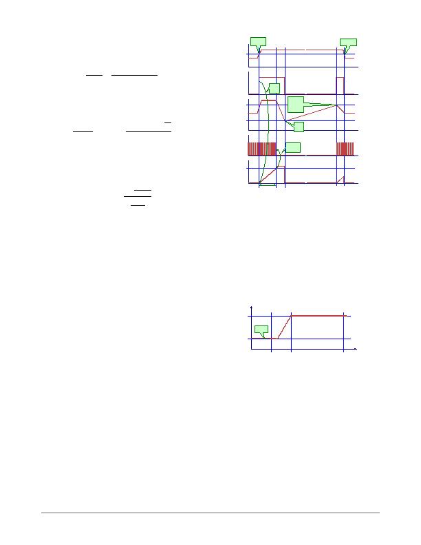
autorecovery operation is depicted in Figure 12.
Figure 12. Operation During Overload
time
Fault Flag
time
V
CC
time
DRV
V
CC(on)
V
CC(off)
Overcurrent
applied
time
Output Load
Max Load
time
Fault Timer
80 ms
Fault
timer
starts
Controller
stops
Fault
disappears
t
FOVLD
Restart
At V
CC(on)
Fault is
reset
Frequency Foldback
In order to improve the efficiency at light load conditions,
the frequency of the internal oscillator is linearly reduced
from its nominal value down to f
OSC(MIN)
(typically
26 kHz). The frequency foldback starts when the voltage on
the FFB pin goes below V
fold
, and is completed before V
FFB
reaches V
FSKIP
. The currentmode control remains active
while the oscillator frequency decreases. This is shown in
Figure 13.
Figure 13. Switching Frequency as V
FFB
Decreases
FFB
Oscillator Frequency
f
OSC
V
FSKIP
V
fold
f
OSC(MIN)
Skip
Skip Cycle Mode with SoftSkip
When the feedback voltage reaches V
FSKIP
while
decreasing, skip mode is activated and the driver stops
switching. While the driver is disabled, V
FFB
begins to rise.
As soon as V
FFB
rises above V
FSKIP
+ V
FSKIP(HYS)
, the
driver starts to switch again, but the duty ratio is gradually
increased from nearly 0% over a short SoftSkip duration
(t
SSKIP
). This is accomplished by comparing the current
相关PDF资料 |
PDF描述 |
|---|---|
| NCP380HMU21AATBG | IC CURRENT LIMIT SWITCH 6-UDFN |
| NCT1008DMT3R2G | TMP DIO MON/SMBUS 4CH 8WDFN |
| NCT210RQR2G | IC TEMP SENSOR LOC/REM 16QSOP |
| NCT214MT3R2G | IC TEMP SENSOR LOC/REM 10WDFN |
| NCT72CMNR2G | IC REMOTE THERMAL SENSOR 8-DFN |
相关代理商/技术参数 |
参数描述 |
|---|---|
| NCP1937A1DR2G | 制造商:ON Semiconductor 功能描述:COMBO PFC & QUAZI FLYBACK - Tape and Reel 制造商:ON Semiconductor 功能描述:REEL / COMBO PFC & QUAZI FLYBACK |
| NCP1937B1DR2G | 制造商:ON Semiconductor 功能描述:COMBO PFC & QUAZI FLYBACK - Tape and Reel |
| NCP1937BADAPGEVB | 制造商:ON Semiconductor 功能描述:ADPTR 90W PFC+QR<10MW - Bulk 制造商:ON Semiconductor 功能描述:BOARD EVAL FOR NCP1937 制造商:ON Semiconductor 功能描述:Power Management IC Development Tools 90 W Adapter PFC+QR 10 MW Eval Brd |
| NCP21WB333 | 制造商:MURATA 制造商全称:Murata Manufacturing Co., Ltd. 功能描述:for Surface Mounting Application |
| NCP21WB333J03RA | 功能描述:热敏电阻 - NTC 33K OHM 5% RoHS:否 制造商:EPCOS 电阻:10 kOhms 功率额定值:150 mW 容差:2 % 端接类型:Radial 系列:B57703M 工作温度范围:- 55 C to + 125 C |
发布紧急采购,3分钟左右您将得到回复。