- 您现在的位置:买卖IC网 > PDF目录378041 > PBL386652QNS (ERICSSON) Subscriber Line Interface Circuit PDF资料下载
参数资料
| 型号: | PBL386652QNS |
| 厂商: | ERICSSON |
| 英文描述: | Subscriber Line Interface Circuit |
| 中文描述: | 用户线接口电路 |
| 文件页数: | 13/18页 |
| 文件大小: | 184K |
| 代理商: | PBL386652QNS |
PBL 386 65/2
13
Preliminary
V
is defined as the battery voltage on
the VBat terminal minus the Battery Over
Head voltage, V
BOH
, according to the equa-
tion
V
TRMax
(at I
L
= 0 mA) = |V
Bat
| - V
BOH
Refer to table 2 for typical V
BOH
values.
V
BOH
(typ) [V]
AOV-PIN NC
AOV-PIN to AGND
Table 2. The battery overhead voltages
at open loop conditions.
4.2
3.2
Resistive Loop Feed Region
The resistive loop feed (reference D in
figure 15) is programmed by connecting a
resistor R
, between terminals PSG and
VBAT according to the equation
R
= R
SG
+ 40 + 2R
F
400
Constant Current Region
The current limit (reference C in figure 15)
is adjusted by connecting a resistor, R
,
between terminal PLC and ground accord-
ing to the equation:
LC
= 500
14
R
LProg
Battery Switch (VBAT2)
To reduce short loop power dissipation, a
second lower battery voltage may be con-
nected to the device through an external
diode at terminal VBAT2. The SLIC auto-
matically switches between the two battery
supply voltages without need for external
control. The silent battery switching occurs
when the line voltage passes the value
V
= |V
| - 40
I
- 6
15
Connect the terminal VBAT2 to the sec-
ond power supply via the diode D
B2
in figure
14.
An optional diode D
connected between
terminal VBAT and the VB2 power supply,
see figure 13, will make sure that the SLIC
continues to work on the second battery
even if the first battery voltage disappears.
If the V
voltage is not available, an
optional external power management re-
sistor, R
, may be connected between the
VBAT2-pin and the VBAT-pin to move pow-
er dissipation outside the chip.
Calculation of the external power man-
agement resistor to locate the maximum
power dissipation outside the SLIC is ac-
cording to:
PM
= |V
Bat
| - 3
R
LProg
Metering Applications, TTX
It is very easy to use PBL 386 65/2 in
metering applications; simply connect a
suitable resistor (R
) in series with a
capacitor (C
) between pin RSN and the
metering source. Capacitor C
decou-
ples all DC-voltages that may be superim-
posed on the metering signal. Choose 1/
(2
π
R
C
)
≥
5kHz to suppress low fre-
quency disturbances from the metering
puls generator. The metering signal gain
can be calculated from the equation:
4-2TTX
= V
TR
=
G
TTX
Z
T
Z
LTTX
R
TTX
Z
T
- G
2-4S
(Z
LTTX
+ 2R
F
)
α
RSN
where:
V
TTX
is the voltage of the signal at the
metering generator,
is the line impedance seen by the
12 or 16 kHz metering signal,
is the transmit gain through the SLIC,
i e -0.5. (Phase shift 180
°
)
Z
LTTX
G
2-4S
In metering applications with resistive
line feeding characteristic and very strict
requirements (as mentioned earlier in chap-
ter “AOV in resistive loop feed region“), the
metering signal level should not exceed 2.2
V
RMS 16
, since a reduction of the line current
will generate a transversal, and sometimes
audible, signal (which is not the case in the
constant current region).
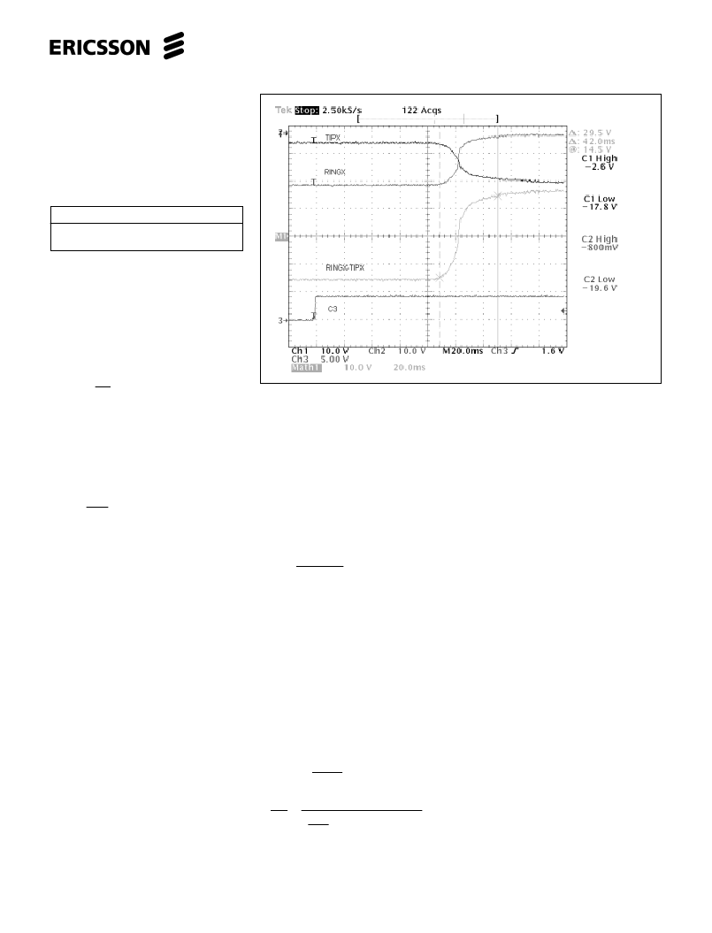
Silent Polarity Reversal
The reversal time is set by a capacitor, C
between the pin SPR and AGND. The
reversal has a setup time and reversal time
see figure 12.
The setup time is different in Active- to
Reversal-state and Reversal- to Active state
but the silent polarity reversal time is the
same Active- to Reversal-state and Rever-
sal- to Active state. To calculate the silent
polarity reversal time use following for-
mula:
t
r
=C
SPR
.
9500
Figure 12. Silent Polarity Reversal
相关PDF资料 |
PDF描述 |
|---|---|
| PBL386652QNT | Subscriber Line Interface Circuit |
| PBL38665-2 | Subscriber Line Interface Circuit |
| PBL386652 | Subscriber Line Interface Circuit |
| PBL386652SHT | Subscriber Line Interface Circuit |
| PBL388121SOT | Voice-switch circuit for Handsfree speakerphone TAM |
相关代理商/技术参数 |
参数描述 |
|---|---|
| PBL386652QNT | 制造商:ERICSSON 制造商全称:Ericsson 功能描述:Subscriber Line Interface Circuit |
| PBL386652SHT | 制造商:ERICSSON 制造商全称:Ericsson 功能描述:Subscriber Line Interface Circuit |
| PBL38780/1QSD | 制造商:Rochester Electronics LLC 功能描述:- Bulk |
| PBL387821QSD | 制造商:Rochester Electronics LLC 功能描述:- Bulk 制造商:Infineon Technologies AG 功能描述: |
| PBL38812 | 制造商:ERICSSON 制造商全称:Ericsson 功能描述:Voice-switch circuit for Handsfree speakerphone TAM |
发布紧急采购,3分钟左右您将得到回复。