- 您现在的位置:买卖IC网 > PDF目录69042 > PC34703PNB/R2 (FREESCALE SEMICONDUCTOR INC) 18 A SWITCHING REGULATOR, 400 kHz SWITCHING FREQ-MAX, PQCC33 PDF资料下载
参数资料
| 型号: | PC34703PNB/R2 |
| 厂商: | FREESCALE SEMICONDUCTOR INC |
| 元件分类: | 稳压器 |
| 英文描述: | 18 A SWITCHING REGULATOR, 400 kHz SWITCHING FREQ-MAX, PQCC33 |
| 封装: | 10 X 10 MM, 2.1 MM HEIGHT, 0.8 PITCH, PLASTIC, QFN-33 |
| 文件页数: | 9/46页 |
| 文件大小: | 2509K |
| 代理商: | PC34703PNB/R2 |
第1页第2页第3页第4页第5页第6页第7页第8页当前第9页第10页第11页第12页第13页第14页第15页第16页第17页第18页第19页第20页第21页第22页第23页第24页第25页第26页第27页第28页第29页第30页第31页第32页第33页第34页第35页第36页第37页第38页第39页第40页第41页第42页第43页第44页第45页第46页
Analog Integrated Circuit Device Data
Freescale Semiconductor
17
34703
FUNCTIONAL DESCRIPTION
INTRODUCTION
FUNCTIONAL DESCRIPTION
INTRODUCTION
The 34703 power supply integrated circuit provides the
means to efficiently supply the Power QUICC and other
families of Freescale microprocessors. It incorporates a high-
performance synchronous buck regulator, supplying the
microprocessor’s core, and a low dropout (LDO) linear
regulator providing the microprocessor I/O and bus voltages.
This device incorporates many advanced features; e.g.,
precisely maintained up/down power sequencing, ensuring
the proper operation and protection of the CPU and power
system. At the same time, it provides high flexibility of
configuration, allowing the maximum optimization of the
power supply system.
FUNCTIONAL TERMINAL DESCRIPTION
BOOST VOLTAGE TERMINAL (VBST)
Internal boost regulator output voltage. The internal boost
regulator provides a 45 mA output current to supply the drive
circuits for the integrated power MOSFETs and the external
N-channel power MOSFET of the linear regulator. The
voltage at the VBST terminal is 8.0 V nominal.
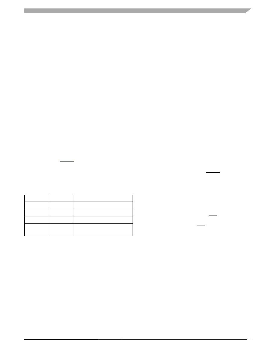
ENABLE 1 AND 2 TERMINALS (EN1 AND EN2)
These two terminals permit positive logic control of the
Enable function and selection of the Power Sequencing
mode concurrently. Table 5 depicts the EN1 and EN2
function and Power Sequencing mode selection.
Both EN1 and EN2 terminals have internal pulldown
resistors and both can withstand a short circuit to the supply
voltage, 13.5 V.
CLOCK SELECTION TERMINAL (CLKSEL)
This terminal sets the CLKSYN terminal as either an
oscillator output or a synchronization input terminal. The
CLKSEL terminal is also used for the I2C address selection.
INPUT VOLTAGE 1 TERMINAL (VIN1)
The input supply terminal for the integrated circuit. The
internal circuits of the IC are supplied through this terminal.
SERIAL CLOCK TERMINAL (SCL)
I2C bus terminal. Serial clock.
OSCILLATOR FREQUENCY TERMINAL (FREQ)
This switcher frequency selection terminal can be adjusted
by connecting external resistor RF to the FREQ terminal. The
default switching frequency (FREQ terminal left open or tied
to VDDI) is set to 300 kHz.
ADDRESS TERMINAL (ADDR)
The ADDR terminal is used to set the address of the
device when used in an I2C communication. This terminal
can either be tied to VDDI or grounded through a 10 k
resistor. Refer to I2C Bus Operation on page 27 for more
information on this terminal.
RESET OUTPUT TERMINAL (RESET)
The Reset Control circuit monitors both the switching
regulator and the LDO feedback voltages. It is an open drain
output and has to be pulled up to some supply voltage (e.g.,
the output of the LDO) by an external resistor.
The Reset Control circuit supervises both output
voltages—the linear regulator output VLDO and the switching
regulator output VOUT. When either of these two regulators
is out of regulation (high or low), the RST terminal is pulled
low. There is a 20 s delay filter preventing erroneous resets.
During power-up sequencing, RST is held low until the Reset
Timer times out.
LINEAR COMPENSATION TERMINAL (LCMP)
Linear regulator compensation terminal.
CURRENT SENSE TERMINAL (ISNS)
Current sense terminal of the LDO. Overcurrent protection
of the linear regulator external power MOSFET. The voltage
drop over the LDO current sense resistor RS is sensed
between the ISNS and LDO terminals. The LDO current limit
can be adjusted by selecting the proper value of the current
sensing resistor RS.
LINEAR REGULATOR TERMINAL (LDO)
Input terminal of the linear regulator power sequence
control circuit.
Table 5. Operating Mode Selection
EN1
EN2
Operating Mode
0
Regulators Disabled
0
1
Standard Power Sequencing
1
0
Inverted Power Sequencing
1
No Power Sequencing,
Regulators Enabled
相关PDF资料 |
PDF描述 |
|---|---|
| PC34708VMR2 | 1-CHANNEL POWER SUPPLY MANAGEMENT CKT, PBGA206 |
| PC34708VM | 1-CHANNEL POWER SUPPLY MANAGEMENT CKT, PBGA206 |
| PC34708VK | 1-CHANNEL POWER SUPPLY MANAGEMENT CKT, PBGA206 |
| PCF1252-6T | 1-CHANNEL POWER SUPPLY SUPPORT CKT, PDSO8 |
| PCF1252-8T-T | 1-CHANNEL POWER SUPPLY SUPPORT CKT, PDSO8 |
相关代理商/技术参数 |
参数描述 |
|---|---|
| PC34708VK | 制造商:Freescale Semiconductor 功能描述:PMIC 5S 6LDO BST 10BTADC - Bulk |
| PC34708VM | 制造商:Freescale Semiconductor 功能描述:PMIC 5S 6LDO BST 10BTADC - Bulk |
| PC34709VK | 制造商:Freescale Semiconductor 功能描述:PMIC 5SW,6 LDO,BST - Bulk |
| PC34709VKR2 | 制造商:Freescale Semiconductor 功能描述:PMIC 5SW,6 LDO,BST - Tape and Reel |
| PC34710EW | 制造商:MOTOROLA 制造商全称:Motorola, Inc 功能描述:Adjustable Dual Output Switching Power Supply |
发布紧急采购,3分钟左右您将得到回复。