- 您现在的位置:买卖IC网 > Datasheet目录349 > PCA9553DP/01,118 (NXP Semiconductors)IC LED DRIVER LINEAR 8-TSSOP Datasheet资料下载
参数资料
| 型号: | PCA9553DP/01,118 |
| 厂商: | NXP Semiconductors |
| 文件页数: | 8/26页 |
| 文件大小: | 0K |
| 描述: | IC LED DRIVER LINEAR 8-TSSOP |
| 产品培训模块: | LED Controllers I²C Bus Fundamentals |
| 标准包装: | 1 |
| 拓扑: | 开路漏极,PWM |
| 输出数: | 4 |
| 内部驱动器: | 是 |
| 类型 - 主要: | LED 闪烁器 |
| 频率: | 400kHz |
| 电源电压: | 2.3 V ~ 5.5 V |
| 安装类型: | 表面贴装 |
| 封装/外壳: | 8-TSSOP,8-MSOP(0.118",3.00mm 宽) |
| 供应商设备封装: | 8-TSSOP |
| 包装: | 标准包装 |
| 工作温度: | -40°C ~ 85°C |
| 产品目录页面: | 844 (CN2011-ZH PDF) |
| 其它名称: | 568-3392-6 |
�� �
�
�NXP� Semiconductors�
�PCA9553�
�4-bit� I� 2� C-bus� LED� driver� with� programmable� blink� rates�
�7.4� Pins� used� as� general� purpose� I/Os�
�LED� pins� not� used� to� control� LEDs� can� be� used� as� general� purpose� I/Os.�
�For� use� as� input:� Set� LEDn� to� high-impedance� (01)� and� then� read� the� pin� state� via� the�
�Input� register.�
�For� use� as� output:� Connect� external� pull-up� resistor� to� the� pin� and� size� it� according� to� the�
�DC� recommended� operating� characteristics.� LED� output� pin� is� HIGH� when� the� output� is�
�programmed� as� high-impedance,� and� LOW� when� the� output� is� programmed� LOW� through�
�the� ‘LED� selector’� register.� The� output� can� be� pulse-width� controlled� when� PWM0� or�
�PWM1� are� used.�
�7.5� Power-on� reset�
�When� power� is� applied� to� V� DD� ,� an� internal� Power-On� Reset� (POR)� holds� the� PCA9553� in�
�a� reset� condition� until� V� DD� has� reached� V� POR� .� At� that� point,� the� reset� condition� is� released�
�and� the� PCA9553� registers� are� initialized� to� their� default� states,� with� all� outputs� in� the� OFF�
�state.� Thereafter,� V� DD� must� be� lowered� below� 0.2� V� to� reset� the� device.�
�8.� Characteristics� of� the� I� 2� C-bus�
�The� I� 2� C-bus� is� for� 2-way,� 2-line� communication� between� different� ICs� or� modules.� The� two�
�lines� are� a� serial� data� line� (SDA)� and� a� serial� clock� line� (SCL).� Both� lines� must� be�
�connected� to� a� positive� supply� via� a� pull-up� resistor� when� connected� to� the� output� stages�
�of� a� device.� Data� transfer� may� be� initiated� only� when� the� bus� is� not� busy.�
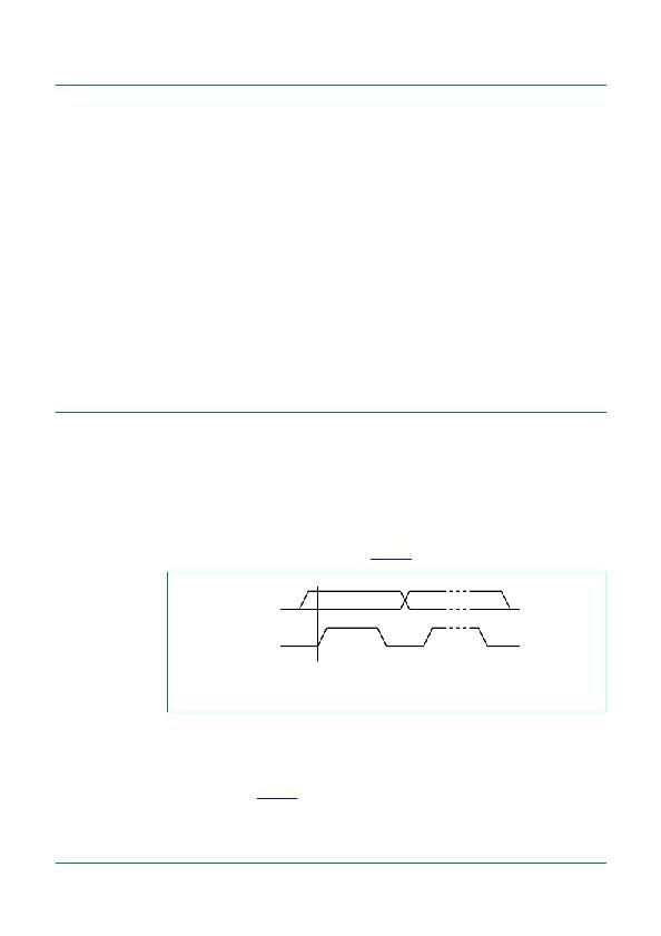
�8.1� Bit� transfer�
�One� data� bit� is� transferred� during� each� clock� pulse.� The� data� on� the� SDA� line� must� remain�
�stable� during� the� HIGH� period� of� the� clock� pulse� as� changes� in� the� data� line� at� this� time�
�will� be� interpreted� as� control� signals� (see� Figure� 8� ).�
�SDA�
�SCL�
�data� line�
�stable;�
�change�
�of� data�
�Fig� 8.�
�Bit� transfer�
�data� valid�
�allowed�
�mba607�
�8.1.1� START� and� STOP� conditions�
�Both� data� and� clock� lines� remain� HIGH� when� the� bus� is� not� busy.� A� HIGH-to-LOW�
�transition� of� the� data� line� while� the� clock� is� HIGH� is� de?ned� as� the� START� condition� (S).� A�
�LOW-to-HIGH� transition� of� the� data� line� while� the� clock� is� HIGH� is� de?ned� as� the� STOP�
�condition� (P)� (see� Figure� 9� ).�
�PCA9553_6�
�?� NXP� B.V.� 2008.� All� rights� reserved.�
�Product� data� sheet�
�Rev.� 06� —� 29� December� 2008�
�8� of� 26�
�相关PDF资料 |
PDF描述 |
|---|---|
| PCA9624PW,118 | IC LED DRIVER RGBA 24-TSSOP |
| PCA9625D/S911,518 | IC LED DRIVER RGBA 32-SOIC |
| PCA9626BS,518 | IC LED DRIVER RGBA 48HVQFN |
| PCA9632DP2,118 | IC LED DRIVER RGBA 10-TSSOP |
| PCA9633BS,118 | IC LED DRIVER RGBA 16-HVQFN |
相关代理商/技术参数 |
参数描述 |
|---|---|
| PCA9553DP02 | 制造商:PHILIPS 制造商全称:NXP Semiconductors 功能描述:4-bit I2C LED driver with programmable blink rates |
| PCA9553TK | 制造商:PHILIPS 制造商全称:NXP Semiconductors 功能描述:4-bit I2C-bus LED driver with programmable blink rates |
| PCA9553TK,118 | 功能描述:LED照明驱动器 4BIT I2C FM OD LED RoHS:否 制造商:STMicroelectronics 输入电压:11.5 V to 23 V 工作频率: 最大电源电流:1.7 mA 输出电流: 最大工作温度: 安装风格:SMD/SMT 封装 / 箱体:SO-16N |
| PCA9553TK/02 | 制造商:PHILIPS 制造商全称:NXP Semiconductors 功能描述:4-bit I2C-bus LED driver with programmable blink rates |
| PCA9553TK/02,118 | 功能描述:LED照明驱动器 LED DRVR 4Segment 2.5V/3.3V/5V 8-Pin RoHS:否 制造商:STMicroelectronics 输入电压:11.5 V to 23 V 工作频率: 最大电源电流:1.7 mA 输出电流: 最大工作温度: 安装风格:SMD/SMT 封装 / 箱体:SO-16N |
发布紧急采购,3分钟左右您将得到回复。