- 您现在的位置:买卖IC网 > PDF目录69043 > PD70201ILQ-TR (MICROSEMI CORP-ANALOG MIXED SIGNAL GROUP) SWITCHING CONTROLLER, 500 kHz SWITCHING FREQ-MAX, PQCC32 PDF资料下载
参数资料
| 型号: | PD70201ILQ-TR |
| 厂商: | MICROSEMI CORP-ANALOG MIXED SIGNAL GROUP |
| 元件分类: | 稳压器 |
| 英文描述: | SWITCHING CONTROLLER, 500 kHz SWITCHING FREQ-MAX, PQCC32 |
| 封装: | 5 X 5 MM, ROHS COMPLIANT, PLASTIC, QFN-32 |
| 文件页数: | 3/19页 |
| 文件大小: | 416K |
| 代理商: | PD70201ILQ-TR |
PD70101 & PD70201
PRELIMINARY DATA SHEET
Copyright 2010
Microsemi
Page 11
Rev. 0.6, 21-Jan-2011
Analog Mixed Signal Group
11861 Western Avenue, Garden Grove, CA 92841; 714-898-8121; Fax: 714-893-2570
P
D
7
0
1
0
1
&
P
D
7
0
2
0
1
PD70101 / PD70201: IEEE 802.3 af/at
Power Over Ethernet PD Controller
TM
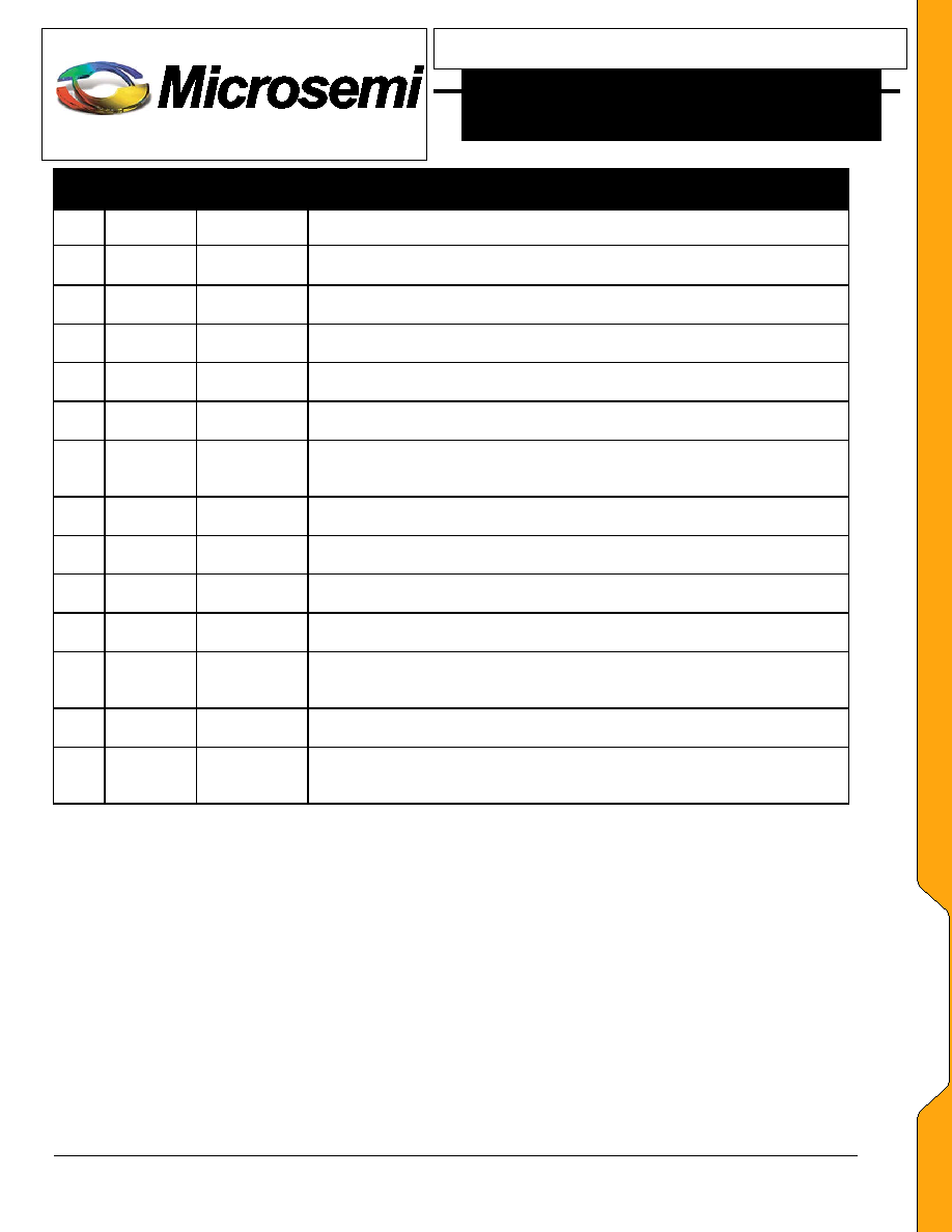
P D 7 0 1 0 1 / P D 7 0 2 0 1 P I N D E S C R I P T I O N
Pin
PD70101 Pin
Name
PD70201 Pin
Name
Description
21
DAO
Differential
Amplifier
Output.
Connect
to
FB
(externally)
via
a
1.2k
resistor for Non-Isolated Direct Buck Converter.
22
FB
Inverting Input of the Error Amplifier. Connect to SS for Isolated DC-DC.
Connect to RC compensation networks for Non-isolated DC-DC
23
GND
This is Analog GND. Connect to a local AGND plane. Soft-start capacitor
and the frequency setting resistor return to this local GND plane.
24
VL
5V (GND reference) internal LDO Output. Connect a 1F or higher ceramic
cap from VL to GND.
25
SG
Secondary Gate Driver. Output is the compliment of PG output. Leave
open (NC) if not used. SG is low when in Low Power Skip Mode.
26
PGND
This is the Power Ground. Connect to a local PGND plane. Input, VCC
decoupling capacitors, PG and SG drivers, Primary current sense resistor
return to this PGND
27
CSN
Negative Input of the Current Sense Amplifier. Kelvin connect to the PGND
side of the primary current sense resistor
28
CSP
Negative Input of the Current Sense Amplifier. Kelvin connect to the Non-
PGND side of the primary current sense resistor
29
PG
Primary Gate Driver. Connect to the gate of the primary side Power
MOSFET, directly or via a resistor
30
VH
5V High side ( VCC reference) internal LDO Output. Connect a 0.1F or
higher ceramic cap from VH to VCC.
31
VCC
Input Supply to the DC-DC Controller. Connect a 4.7F or higher ceramic
capacitor from this pin to PGND. Alternately an parallel combination of 1F
ceramic and an greater than 10F electrolytic capacitor can be used.
32
VPP
This is the positive terminal of the POE input port. Connect to the positive
terminal of the input bridges at the CDET positive side
EP
Exposed
Pad
Exposed Pad
Thermal Pad; electrically connected to VPN_IN. For proper thermal
management should be tied to a large copper fill or plane that is electrically
connected to VPN_IN.
相关PDF资料 |
PDF描述 |
|---|---|
| PD70101ILQ-TR | SWITCHING CONTROLLER, 500 kHz SWITCHING FREQ-MAX, PQCC32 |
| PD70101ILQ | SWITCHING CONTROLLER, 500 kHz SWITCHING FREQ-MAX, PQCC32 |
| PDT003A0X3-SRZ | 1-OUTPUT DC-DC REG PWR SUPPLY MODULE |
| PDT003A0X43-SRZ | 1-OUTPUT DC-DC REG PWR SUPPLY MODULE |
| PE3336-52 | PHASE LOCKED LOOP, 3000 MHz, QCC44 |
相关代理商/技术参数 |
参数描述 |
|---|---|
| PD70210ILD-TR | 制造商:Microsemi Corporation 功能描述:IC PD FRONT END CTLR 16DFN |
| PD7035 | 制造商:MITSUBISHI 制造商全称:Mitsubishi Electric Semiconductor 功能描述:FOR OPTICAL COMMUNICATION |
| PD7087 | 制造商:MITSUBISHI 制造商全称:Mitsubishi Electric Semiconductor 功能描述:InGaAs PIN PHOTO DIODES |
| PD7088 | 制造商:MITSUBISHI 制造商全称:Mitsubishi Electric Semiconductor 功能描述:InGaAs PIN PHOTO DIODES |
| PD708C7 | 制造商:MITSUBISHI 制造商全称:Mitsubishi Electric Semiconductor 功能描述:InGaAs PIN PHOTO DIODES |
发布紧急采购,3分钟左右您将得到回复。