- 您现在的位置:买卖IC网 > PDF目录69043 > PD70201ILQ-TR (MICROSEMI CORP-ANALOG MIXED SIGNAL GROUP) SWITCHING CONTROLLER, 500 kHz SWITCHING FREQ-MAX, PQCC32 PDF资料下载
参数资料
| 型号: | PD70201ILQ-TR |
| 厂商: | MICROSEMI CORP-ANALOG MIXED SIGNAL GROUP |
| 元件分类: | 稳压器 |
| 英文描述: | SWITCHING CONTROLLER, 500 kHz SWITCHING FREQ-MAX, PQCC32 |
| 封装: | 5 X 5 MM, ROHS COMPLIANT, PLASTIC, QFN-32 |
| 文件页数: | 7/19页 |
| 文件大小: | 416K |
| 代理商: | PD70201ILQ-TR |
PD70101 & PD70201
PRELIMINARY DATA SHEET
Copyright 2010
Microsemi
Page 15
Rev. 0.6, 21-Jan-2011
Analog Mixed Signal Group
11861 Western Avenue, Garden Grove, CA 92841; 714-898-8121; Fax: 714-893-2570
P
D
7
0
1
0
1
&
P
D
7
0
2
0
1
PD70101 / PD70201: IEEE 802.3 af/at
Power Over Ethernet PD Controller
TM
T H E O R Y O F O P E R A T I O N
Internal logic monitors VPP to VPN_IN voltage and
keeps the MOSFET in a high impedance state until
VPP to VPN_IN voltage reaches turn-on threshold of
36V to 42V. Once VPP to VPN_IN voltage exceeds
this threshold, the MOSFET is switched into one of
two modes.
Mode into which the MOSFET is switched is
determined by the voltage developed across the
MOSFET, or put another way, the VPN_OUT to
VPN_IN differential voltage. Two modes are defined
below:
Isolation Switch Modes
VPN_OUT
to VPN_IN
Mode
Description
≥ 0.7V
Soft Start
Mode
Limits VPN_OUT current to
240mA (typical)
≤ 0.7V
Normal
Operatin
g Mode
Limits VPN_OUT current to
1.8A (typical)
By controlling the MOSFET current based on
VPN_OUT
to
VPN_IN
voltage,
inrush
currents
generated by fully discharged bulk capacitors can be
limited. This method limits current to a maximum of
350mA, compliant with IEEE 802.3af/at specification.
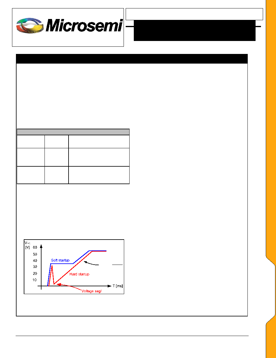
Soft Start current limiting is required to reduce
occurrences of voltage sag at the PD input during
device power-up. A comparison is shown in Figure 3.
DC
Inrush
C
I
Slope
/
Figure 3. Comparison of input voltages without Soft Start
(Hard startup), and with Soft Start (Soft startup).
Once bulk capacitance has charged up to a point
where VPN_OUT to VPN_IN differential voltage is less
than 0.7V, the isolation MOSFET is switched into
normal operating mode with MOSFET current limit set
at 1.8A (typical), to provide overcurrent protection.
PD70101 and PD70201 ICs are different in their
respective
isolation
MOSFET’s
continuous
current
handling capability:
PD70101: 450mA (max.)
PD70201: 1123mA (max.)
An adequate heatsink for the PD70101/PD70201 IC’s
exposed pad must be provided to achieve these current
levels without damaging the IC. A large, heavy copper
fill area and/or a heavy ground plane with Thermal Vias
is recommended.
Internal logic monitoring VPP to VPN_IN will place the
isolation switch MOSFET in a high impedance state if
voltage between VPP and VPN_IN drops below 31V to
34V.
OVER-CURRENT PROTECTION
An
over-current
protection
is
provided
on
the
PD70101/PD70201
IC
using
the
Isolation
Switch
MOSFET, which limits the VPN_OUT current to 1.8A
during normal operation.
See previous description of
Soft Start.
POWER GOOD
During Soft Start mode, the
PD70101/PD70201 IC
monitors VPN_OUT to VPN_IN differential voltage.
When this voltage is less than 0.7V (max.), the IC
enters normal operation mode and the isolation switch
current limit is increased to 1.8A (typical). At this same
0.7V (max.) threshold the Power Good signal is
asserted by means of an open drain MOSFET between
PGOOD and VPN_OUT.
PGOOD pin is active low; a low impedance state
between PGOOD and VPN_OUT indicates the Soft
Start mode has finished and the isolation switch has
transitioned into normal operating mode.
PGOOD MOSFET can handle current of 5mA and can
be pulled up to VPP.
相关PDF资料 |
PDF描述 |
|---|---|
| PD70101ILQ-TR | SWITCHING CONTROLLER, 500 kHz SWITCHING FREQ-MAX, PQCC32 |
| PD70101ILQ | SWITCHING CONTROLLER, 500 kHz SWITCHING FREQ-MAX, PQCC32 |
| PDT003A0X3-SRZ | 1-OUTPUT DC-DC REG PWR SUPPLY MODULE |
| PDT003A0X43-SRZ | 1-OUTPUT DC-DC REG PWR SUPPLY MODULE |
| PE3336-52 | PHASE LOCKED LOOP, 3000 MHz, QCC44 |
相关代理商/技术参数 |
参数描述 |
|---|---|
| PD70210ILD-TR | 制造商:Microsemi Corporation 功能描述:IC PD FRONT END CTLR 16DFN |
| PD7035 | 制造商:MITSUBISHI 制造商全称:Mitsubishi Electric Semiconductor 功能描述:FOR OPTICAL COMMUNICATION |
| PD7087 | 制造商:MITSUBISHI 制造商全称:Mitsubishi Electric Semiconductor 功能描述:InGaAs PIN PHOTO DIODES |
| PD7088 | 制造商:MITSUBISHI 制造商全称:Mitsubishi Electric Semiconductor 功能描述:InGaAs PIN PHOTO DIODES |
| PD708C7 | 制造商:MITSUBISHI 制造商全称:Mitsubishi Electric Semiconductor 功能描述:InGaAs PIN PHOTO DIODES |
发布紧急采购,3分钟左右您将得到回复。