参数资料
| 型号: | PIC12F683T-E/MF |
| 厂商: | Microchip Technology |
| 文件页数: | 164/176页 |
| 文件大小: | 0K |
| 描述: | IC MCU FLASH 2KX14 8DFN |
| Digi-Key 应用说明: | AN0005 PWM Example with Microchip's CCP Module AN0005 Example Code |
| 标准包装: | 3,300 |
| 系列: | PIC® 12F |
| 核心处理器: | PIC |
| 芯体尺寸: | 8-位 |
| 速度: | 20MHz |
| 外围设备: | 欠压检测/复位,POR,PWM,WDT |
| 输入/输出数: | 5 |
| 程序存储器容量: | 3.5KB(2K x 14) |
| 程序存储器类型: | 闪存 |
| EEPROM 大小: | 256 x 8 |
| RAM 容量: | 128 x 8 |
| 电压 - 电源 (Vcc/Vdd): | 2 V ~ 5.5 V |
| 数据转换器: | A/D 4x10b |
| 振荡器型: | 内部 |
| 工作温度: | -40°C ~ 125°C |
| 封装/外壳: | 8-VDFN 裸露焊盘 |
| 包装: | 带卷 (TR) |
| 配用: | AC164324-ND - MODULE SKT FOR MPLAB 8DFN/16QFN XLT08DFN2-ND - SOCKET TRANSITION ICE 14DIP/8DFN AC162058-ND - HEADER MPLAB ICD2 FOR PIC12F683 I3-DB12F683-ND - BOARD DAUGHTER ICEPIC3 XLT08DFN-ND - SOCKET TRANSITION ICE 8DFN AC164032-ND - ADAPTER PICSTART PLUS 8DFN/DIP AC124001-ND - MODULE SKT PROMATEII 8DIP/SOIC |
第1页第2页第3页第4页第5页第6页第7页第8页第9页第10页第11页第12页第13页第14页第15页第16页第17页第18页第19页第20页第21页第22页第23页第24页第25页第26页第27页第28页第29页第30页第31页第32页第33页第34页第35页第36页第37页第38页第39页第40页第41页第42页第43页第44页第45页第46页第47页第48页第49页第50页第51页第52页第53页第54页第55页第56页第57页第58页第59页第60页第61页第62页第63页第64页第65页第66页第67页第68页第69页第70页第71页第72页第73页第74页第75页第76页第77页第78页第79页第80页第81页第82页第83页第84页第85页第86页第87页第88页第89页第90页第91页第92页第93页第94页第95页第96页第97页第98页第99页第100页第101页第102页第103页第104页第105页第106页第107页第108页第109页第110页第111页第112页第113页第114页第115页第116页第117页第118页第119页第120页第121页第122页第123页第124页第125页第126页第127页第128页第129页第130页第131页第132页第133页第134页第135页第136页第137页第138页第139页第140页第141页第142页第143页第144页第145页第146页第147页第148页第149页第150页第151页第152页第153页第154页第155页第156页第157页第158页第159页第160页第161页第162页第163页当前第164页第165页第166页第167页第168页第169页第170页第171页第172页第173页第174页第175页第176页
PIC12F683
DS41211D-page 86
2007 Microchip Technology Inc.
12.3.1
POWER-ON RESET
The on-chip POR circuit holds the chip in Reset until
VDD has reached a high enough level for proper
operation. To take advantage of the POR, simply
connect the MCLR pin through a resistor to VDD. This
will eliminate external RC components usually needed
to create Power-on Reset. A maximum rise time for
VDD
is
required.
See
Specifications” for details. If the BOR is enabled, the
maximum rise time specification does not apply. The
BOR circuitry will keep the device in Reset until VDD
(BOR)”).
When the device starts normal operation (exits the
Reset condition), device operating parameters (i.e.,
voltage, frequency, temperature, etc.) must be met to
ensure operation. If these conditions are not met, the
device must be held in Reset until the operating
conditions are met.
For additional information, refer to the Application Note
AN607, “Power-up Trouble Shooting” (DS00607).
12.3.2
MCLR
PIC12F683 has a noise filter in the MCLR Reset path.
The filter will detect and ignore small pulses.
It should be noted that a WDT Reset does not drive
MCLR pin low.
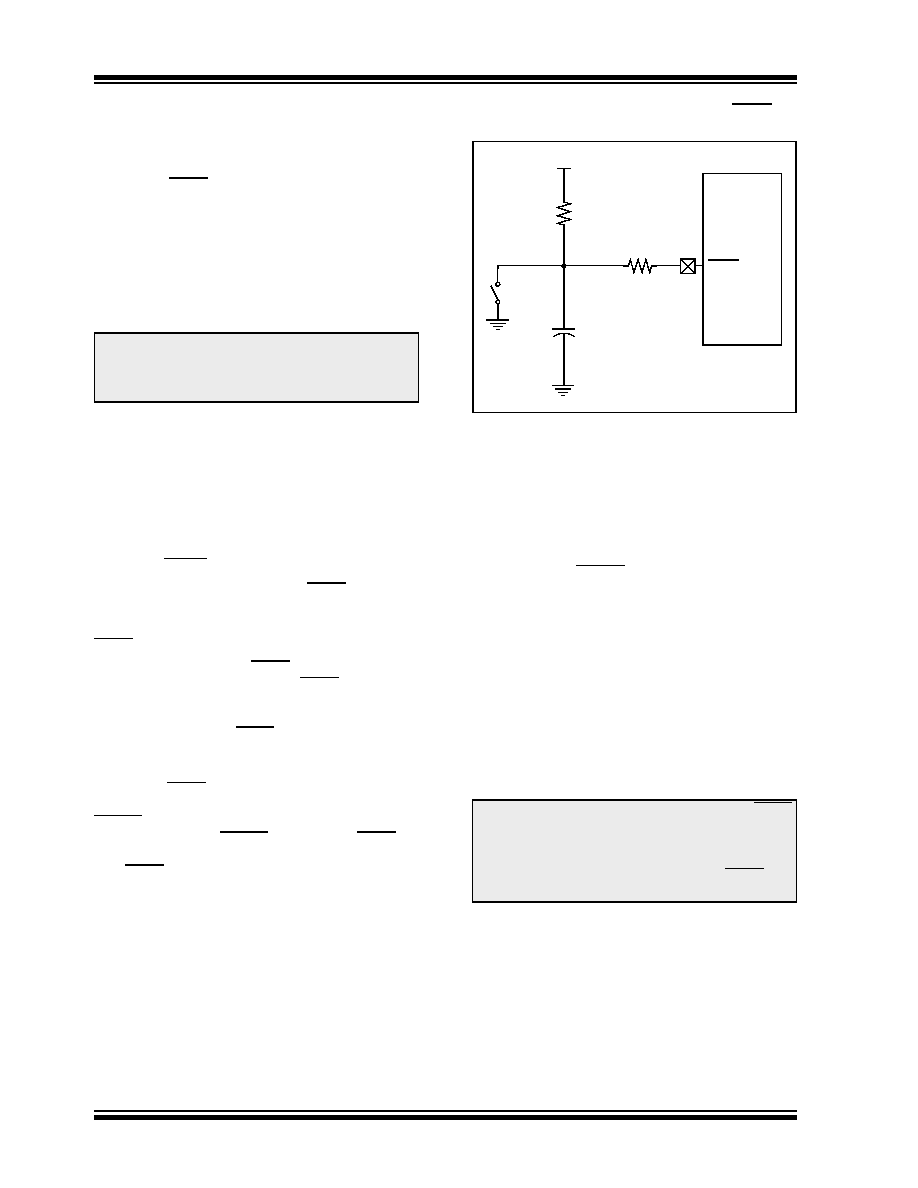
Voltages applied to the MCLR pin that exceed its
specification can result in both MCLR Resets and
excessive current beyond the device specification
during the ESD event. For this reason, Microchip
recommends that the MCLR pin no longer be tied
directly to VDD. The use of an RC network, as shown in
Figure 12-2, is suggested.
An internal MCLR option is enabled by clearing the
MCLRE bit in the Configuration Word register. When
MCLRE = 0, the Reset signal to the chip is generated
internally. When the MCLRE = 1, the GP3/MCLR pin
becomes an external Reset input. In this mode, the
GP3/MCLR pin has a weak pull-up to VDD.
FIGURE 12-2:
RECOMMENDED MCLR
CIRCUIT
12.3.3
POWER-UP TIMER (PWRT)
The Power-up Timer provides a fixed 64 ms (nominal)
time-out on power-up only, from POR or Brown-out
Reset. The Power-up Timer operates from the 31 kHz
LFINTOSC oscillator. For more information, see
Section 3.5 “Internal Clock Modes”. The chip is kept
in Reset as long as PWRT is active. The PWRT delay
allows the VDD to rise to an acceptable level. A
Configuration bit, PWRTE, can disable (if set) or enable
(if cleared or programmed) the Power-up Timer. The
Power-up Timer should be enabled when Brown-out
Reset is enabled, although it is not required.
The Power-up Timer delay will vary from chip-to-chip
due to:
VDD variation
Temperature variation
Process variation
See
DC
parameters
for
details
Note:
The POR circuit does not produce an
internal Reset when VDD declines. To
re-enable the POR, VDD must reach Vss
for a minimum of 100
μs.
Note:
Voltage spikes below VSS at the MCLR
pin, inducing currents greater than 80 mA,
may cause latch-up. Thus, a series resis-
tor of 50-100
Ω should be used when
applying a “low” level to the MCLR pin,
rather than pulling this pin directly to VSS.
VDD
PIC
MCLR
R1
1k
Ω (or greater)
C1
0.1
μF
(optional, not critical)
R2
100
Ω
(needed with capacitor)
SW1
(optional)
MCU
相关PDF资料 |
PDF描述 |
|---|---|
| PIC12HV752-E/P | IC MCU 8BIT 1024B FLASH 8-PDIP |
| PIC12LF1501-E/MC | IC MCU 8BIT 1.75KB FLASH 8DFN |
| PIC12LF1501-I/MF | IC MCU 8BIT 1.75KB FLASH 8-DFN |
| PIC14000-04I/SO | IC MCU OTP 4KX14 A/D 28SOIC |
| PIC16C432T-I/SS | IC MCU CMOS 8BIT 20MHZ 2K 20SSOP |
相关代理商/技术参数 |
参数描述 |
|---|---|
| PIC12F683T-I/MD | 功能描述:8位微控制器 -MCU 3.5KB 128 RAM 6I/O RoHS:否 制造商:Silicon Labs 核心:8051 处理器系列:C8051F39x 数据总线宽度:8 bit 最大时钟频率:50 MHz 程序存储器大小:16 KB 数据 RAM 大小:1 KB 片上 ADC:Yes 工作电源电压:1.8 V to 3.6 V 工作温度范围:- 40 C to + 105 C 封装 / 箱体:QFN-20 安装风格:SMD/SMT |
| PIC12F683T-I/MDQTP | 制造商:MICROCHIP 制造商全称:Microchip Technology 功能描述:8-Pin Flash-Based, 8-Bit CMOS Microcontrollers with nanoWatt Technology |
| PIC12F683T-I/MF | 功能描述:8位微控制器 -MCU 3.5KB 128 RAM 6 I/O RoHS:否 制造商:Silicon Labs 核心:8051 处理器系列:C8051F39x 数据总线宽度:8 bit 最大时钟频率:50 MHz 程序存储器大小:16 KB 数据 RAM 大小:1 KB 片上 ADC:Yes 工作电源电压:1.8 V to 3.6 V 工作温度范围:- 40 C to + 105 C 封装 / 箱体:QFN-20 安装风格:SMD/SMT |
| PIC12F683T-I/MFQTP | 制造商:MICROCHIP 制造商全称:Microchip Technology 功能描述:8-Pin Flash-Based, 8-Bit CMOS Microcontrollers with nanoWatt Technology |
| PIC12F683T-I/P | 制造商:MICROCHIP 制造商全称:Microchip Technology 功能描述:8-Pin Flash-Based, 8-Bit CMOS Microcontrollers with nanoWatt Technology |
发布紧急采购,3分钟左右您将得到回复。