- 您现在的位置:买卖IC网 > PDF目录11355 > PIC18F2480-E/SP (Microchip Technology)IC PIC MCU FLASH 8KX16 28DIP PDF资料下载
参数资料
| 型号: | PIC18F2480-E/SP |
| 厂商: | Microchip Technology |
| 文件页数: | 44/88页 |
| 文件大小: | 0K |
| 描述: | IC PIC MCU FLASH 8KX16 28DIP |
| 产品培训模块: | Asynchronous Stimulus PIC18 J Series MCU Overview |
| 标准包装: | 15 |
| 系列: | PIC® 18F |
| 核心处理器: | PIC |
| 芯体尺寸: | 8-位 |
| 速度: | 25MHz |
| 连通性: | CAN,I²C,SPI,UART/USART |
| 外围设备: | 欠压检测/复位,HLVD,POR,PWM,WDT |
| 输入/输出数: | 25 |
| 程序存储器容量: | 16KB(8K x 16) |
| 程序存储器类型: | 闪存 |
| EEPROM 大小: | 256 x 8 |
| RAM 容量: | 768 x 8 |
| 电压 - 电源 (Vcc/Vdd): | 4.2 V ~ 5.5 V |
| 数据转换器: | A/D 8x10b |
| 振荡器型: | 内部 |
| 工作温度: | -40°C ~ 125°C |
| 封装/外壳: | 28-DIP(0.300",7.62mm) |
| 包装: | 管件 |
| 配用: | DVA18XP280-ND - DEVICE ADAPTER 18F2220 PDIP 28LD |
第1页第2页第3页第4页第5页第6页第7页第8页第9页第10页第11页第12页第13页第14页第15页第16页第17页第18页第19页第20页第21页第22页第23页第24页第25页第26页第27页第28页第29页第30页第31页第32页第33页第34页第35页第36页第37页第38页第39页第40页第41页第42页第43页当前第44页第45页第46页第47页第48页第49页第50页第51页第52页第53页第54页第55页第56页第57页第58页第59页第60页第61页第62页第63页第64页第65页第66页第67页第68页第69页第70页第71页第72页第73页第74页第75页第76页第77页第78页第79页第80页第81页第82页第83页第84页第85页第86页第87页第88页
2010 Microchip Technology Inc.
DS21801F-page 49
MCP2515
7.0
INTERRUPTS
The MCP2515 has eight sources of interrupts. The
CANINTE register contains the individual interrupt
enable bits for each interrupt source. The CANINTF
register contains the corresponding interrupt flag bit for
each interrupt source. When an interrupt occurs, the
INT pin is driven low by the MCP2515 and will remain
low until the interrupt is cleared by the MCU. An
interrupt can not be cleared if the respective condition
still prevails.
It is recommended that the bit modify command be
used to reset flag bits in the CANINTF register rather
than normal write operations. This is done to prevent
unintentionally changing a flag that changes during the
write command, potentially causing an interrupt to be
missed.
It should be noted that the CANINTF flags are
read/write and an interrupt can be generated by the
MCU setting any of these bits, provided the associated
CANINTE bit is also set.
7.1
Interrupt Code Bits
The source of a pending interrupt is indicated in the
CANSTAT.ICOD (interrupt code) bits, as indicated in
Register 10-2. In the event that multiple interrupts
occur, the INT will remain low until all interrupts have
been reset by the MCU. The CANSTAT.ICOD bits will
reflect the code for the highest priority interrupt that is
currently pending. Interrupts are internally prioritized
such that the lower the ICOD value, the higher the
interrupt priority. Once the highest priority interrupt
condition has been cleared, the code for the next
highest priority interrupt that is pending (if any) will be
reflected by the ICOD bits (see Table 7-1). Only those
interrupt sources that have their associated CANINTE
enable bit set will be reflected in the ICOD bits.
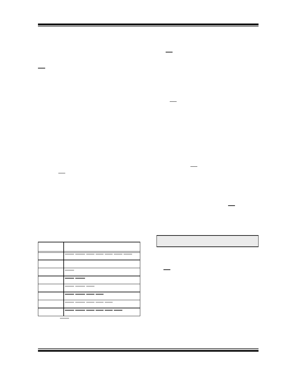
TABLE 7-1:
ICOD<2:0> DECODE
7.2
Transmit Interrupt
When
the
transmit
interrupt
is
enabled
(CANINTE.TXnIE = 1), an interrupt will be generated on
the INT pin once the associated transmit buffer
becomes empty and is ready to be loaded with a new
message. The CANINTF.TXnIF bit will be set to indicate
the source of the interrupt. The interrupt is cleared by
clearing the TXnIF bit.
7.3
Receive Interrupt
When
the
receive
interrupt
is
enabled
(CANINTE.RXnIE = 1), an interrupt will be generated
on the INT pin once a message has been successfully
received and loaded into the associated receive buffer.
This interrupt is activated immediately after receiving
the EOF field. The CANINTF.RXnIF bit will be set to
indicate the source of the interrupt. The interrupt is
cleared by clearing the RXnIF bit.
7.4
Message Error Interrupt
When an error occurs during the transmission or
reception of a message, the message error flag
(CANINTF.MERRF)
will
be
set
and,
if
the
CANINTE.MERRE bit is set, an interrupt will be
generated on the INT pin. This is intended to be used
to facilitate baud rate determination when used in
conjunction with Listen-only mode.
7.5
Bus Activity Wakeup Interrupt
When the MCP2515 is in Sleep mode and the bus activ-
ity wakeup interrupt is enabled (CANINTE.WAKIE = 1),
an interrupt will be generated on the INT pin and the
CANINTF.WAKIF bit will be set when activity is detected
on the CAN bus. This interrupt causes the MCP2515 to
exit Sleep mode. The interrupt is reset by clearing the
WAKIF bit.
7.6
Error Interrupt
When
the
error
interrupt
is
enabled
(CANINTE.ERRIE = 1), an interrupt is generated on
the INT pin if an overflow condition occurs or if the error
state of the transmitter or receiver has changed. The
Error Flag (EFLG) register will indicate one of the
following conditions.
7.6.1
RECEIVER OVERFLOW
An overflow condition occurs when the MAB has
assembled a valid receive message (the message
meets the criteria of the acceptance filters) and the
receive buffer associated with the filter is not available
for loading of a new message. The associated
EFLG.RXnOVR bit will be set to indicate the overflow
condition. This bit must be cleared by the MCU.
ICOD<2:0>
Boolean Expression
000
ERRWAKTX0TX1TX2RX0RX1
001
ERR
010
ERRWAK
011
ERRWAKTX0
100
ERRWAKTX0TX1
101
ERRWAKTX0TX1TX2
110
ERRWAKTX0TX1TX2RX0
111
ERRWAKTX0TX1TX2RX0RX1
Note:
ERR is associated with CANINTE,ERRIE.
Note:
The MCP2515 wakes up into Listen-only
mode.
相关PDF资料 |
PDF描述 |
|---|---|
| V375A36E600B3 | CONVERTER MOD DC/DC 36V 600W |
| VE-JWH-IX-F1 | CONVERTER MOD DC/DC 52V 75W |
| PIC18F4610-I/ML | IC MCU FLASH 32KX16 44QFN |
| V375A36E600B2 | CONVERTER MOD DC/DC 36V 600W |
| VE-JWF-IX-F4 | CONVERTER MOD DC/DC 72V 75W |
相关代理商/技术参数 |
参数描述 |
|---|---|
| PIC18F2480-I/ML | 功能描述:8位微控制器 -MCU 16 KB 768 RAM 25 I/O RoHS:否 制造商:Silicon Labs 核心:8051 处理器系列:C8051F39x 数据总线宽度:8 bit 最大时钟频率:50 MHz 程序存储器大小:16 KB 数据 RAM 大小:1 KB 片上 ADC:Yes 工作电源电压:1.8 V to 3.6 V 工作温度范围:- 40 C to + 105 C 封装 / 箱体:QFN-20 安装风格:SMD/SMT |
| PIC18F2480-I/SO | 功能描述:8位微控制器 -MCU 16 KB 768 RAM 25 I/O RoHS:否 制造商:Silicon Labs 核心:8051 处理器系列:C8051F39x 数据总线宽度:8 bit 最大时钟频率:50 MHz 程序存储器大小:16 KB 数据 RAM 大小:1 KB 片上 ADC:Yes 工作电源电压:1.8 V to 3.6 V 工作温度范围:- 40 C to + 105 C 封装 / 箱体:QFN-20 安装风格:SMD/SMT |
| PIC18F2480-I/SP | 功能描述:8位微控制器 -MCU 16 KB 768 RAM 25 I/O RoHS:否 制造商:Silicon Labs 核心:8051 处理器系列:C8051F39x 数据总线宽度:8 bit 最大时钟频率:50 MHz 程序存储器大小:16 KB 数据 RAM 大小:1 KB 片上 ADC:Yes 工作电源电压:1.8 V to 3.6 V 工作温度范围:- 40 C to + 105 C 封装 / 箱体:QFN-20 安装风格:SMD/SMT |
| PIC18F2480T-I/ML | 功能描述:8位微控制器 -MCU 16 KB 768 RAM 25 I/O RoHS:否 制造商:Silicon Labs 核心:8051 处理器系列:C8051F39x 数据总线宽度:8 bit 最大时钟频率:50 MHz 程序存储器大小:16 KB 数据 RAM 大小:1 KB 片上 ADC:Yes 工作电源电压:1.8 V to 3.6 V 工作温度范围:- 40 C to + 105 C 封装 / 箱体:QFN-20 安装风格:SMD/SMT |
| PIC18F2480T-I/SO | 功能描述:8位微控制器 -MCU 16 KB 768 RAM 25 I/O RoHS:否 制造商:Silicon Labs 核心:8051 处理器系列:C8051F39x 数据总线宽度:8 bit 最大时钟频率:50 MHz 程序存储器大小:16 KB 数据 RAM 大小:1 KB 片上 ADC:Yes 工作电源电压:1.8 V to 3.6 V 工作温度范围:- 40 C to + 105 C 封装 / 箱体:QFN-20 安装风格:SMD/SMT |
发布紧急采购,3分钟左右您将得到回复。