参数资料
| 型号: | QT60240-ISG QS130 |
| 厂商: | Atmel |
| 文件页数: | 4/26页 |
| 文件大小: | 0K |
| 描述: | SENSOR IC MTRX TOUCH24KEY 32-QFN |
| 标准包装: | 1 |
| 系列: | QMatrix™ |
| 类型: | 电容性 |
| 输入数/键: | 24 键 |
| 分辨率(位): | 10 b |
| 评估套件: | 可供 |
| 数据接口: | I²C,串行,SPI? |
| 电压基准: | 外部 |
| 电源电压: | 1.8V,3.3V,5V |
| 电流 - 电源: | 4.6mA |
| 工作温度: | -40°C ~ 85°C |
| 安装类型: | 表面贴装 |
| 封装/外壳: | 32-VFQFN 裸露焊盘 |
| 供应商设备封装: | 32-QFN(5x5) |
| 包装: | 剪切带 (CT) |
| 其它名称: | 427-1126-1 |
4 Control Commands
4.1 Introduction
The devices feature a set of commands which are used for
control and status reporting.
As well as Table 4.1 refer to Table 6.1, page 21 for further
details.
Read/Write
Setups - refer to Table 5.2 for details
131 to
253
Write
Setups write-unlock. Write 0x55
immediately before writing setups
130
Write
Recalibrate all keys. Write 0x55 to
this address location to recalibrate all
the keys
125
Read
Data for keys 0 to 23, in sequence.
Refer to Table 4.3 for details
4 to 123
Read
Detect status for keys 16 to 23, one
bit per key
3
Read
Detect status for keys 8 to 15, one bit
per key
2
Read
Detect status for keys 0 to 7, one bit
per key
1
Read
Reserved
0
Access
Use
Address
Table 4.1 Memory Map
Poll rate: The host can make use of the CHANGE pin output
to initiate a communication; this will guarant ee the optimal
polling rate.
If the host cannot make use of the CHANGE pin the poll rate
in normal ‘run’ operation should be no faster than once per
matrix scan (see Section 7.4, page 23). Typically 10 to 20ms
is more than fast enough to extract the key status. Anything
faster will not provide new information and will slow down the
chip operation.
Sending or reading the setup block is an exception, in this
case the host can send the data at the maximum possible
rate.
Run Poll Sequence: In normal run mode the host should
limit traffic with a minimalist control structure. The host should
just read the three detect status registers (see Figure 4.1,
page 14).
Repeated Start: Using repeated start is not allowed and can
cause communication failure.
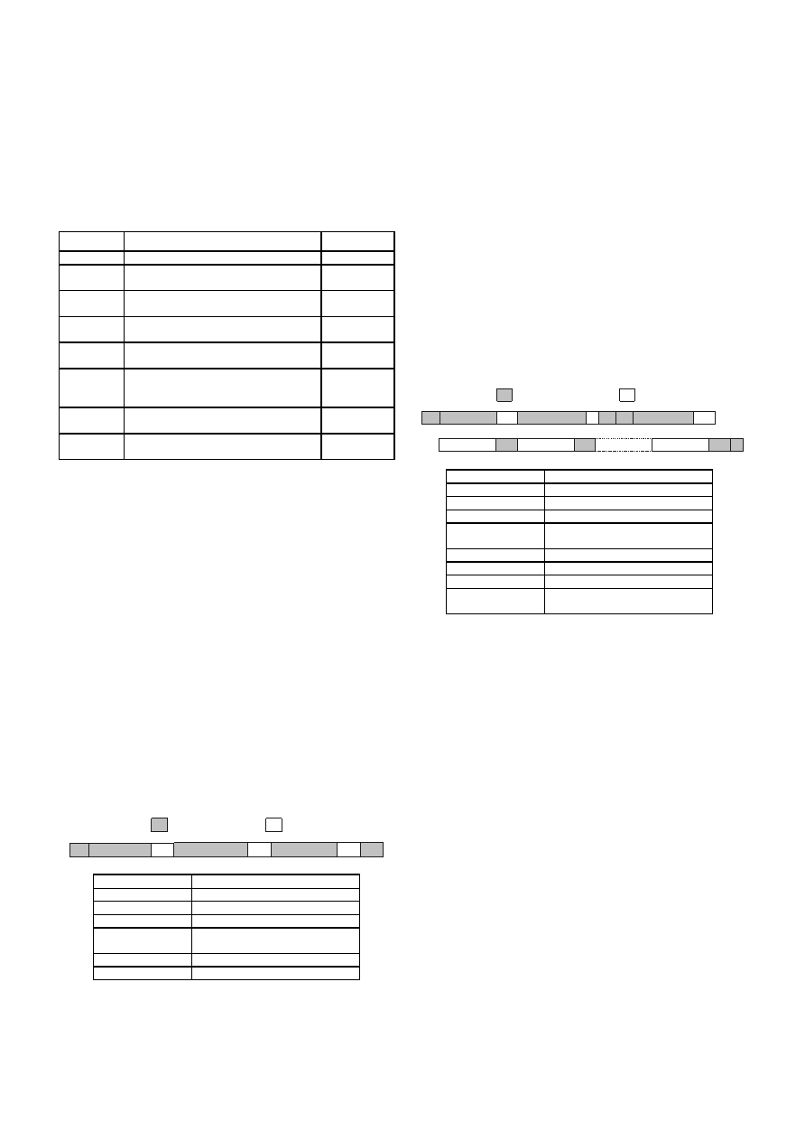
4.2 Writing Data to the Device
The sequence of events required to write data to the device is
shown next.
SLA+W
MemAddress
AA
S
Data
A
P
Host to Device
Device to Host
Stop condition
P
Data to be written
Data
Target memory address within
device
MemAddress
Acknowledge bit
A
Slave address plus write bit
SLA+W
Start condition
S
Key
The host initiates the transfer by sending the START
condition, and follows this by sending the slave address of
the device together with the Write-bit. The device sends an
ACK. The host then sends the memory address within the
device it wishes to write to. The device sends an ACK. The
host transmits one or more data bytes; each will be
acknowledged by the device.
If the host sends more than one data byte, they will be written
to consecutive memory addresses. The device automatically
increments the target memory address after writing each data
byte. After writing the last data byte, the host should send the
STOP condition.
The host should not try to write beyond address 255 because
the device will not increment the internal memory address
beyond this.
4.3 Reading Data From the Device
The sequence of events required to read data from the device
is shown next.
SLA+W
MemAddress
AA
SS
SLA+R
A
P
Host to Device
Device to Host
P
A
/A
Data 1
Data 2
Data n
Not Acknowledge bit/indicates
last byte transmission
/A
Slave address plus read bit
SLA+R
Stop condition
P
Data from device
Data
Target memory address within
device
MemAddress
Acknowledge bit
A
Slave address plus write bit
SLA+W
Start condition
S
Key
The host initiates the transfer by sending the START
condition, and follows this by sending the slave address of
the device together with the Write-bit. The device sends an
ACK. The host then sends the memory address within the
device it wishes to read from. The device sends an ACK.
The host must then send a STOP and a START condition
followed by the slave address again but this time
accompanied by the Read-bit. The device will return an ACK,
followed by a data byte. The host must return either an ACK
or NACK. If the host returns an ACK, the device will
subsequently transmit the data byte from the next address.
Each time a data byte is transmitted, the device automatically
increments the internal address. The device will continue to
return data bytes until the host responds with a NACK. The
host should terminate the transfer by issuing the STOP
condition.
4.4 Report Detections for All Keys
Address 1: detect status for keys 0 to 7
Address 2: detect status for keys 8 to 15
Address 3: detect status for keys 16 to 23
Each location indicates all keys in detection, if any, as a
bitfield; touched keys report as 1’s, untouched or disabled
keys report as 0’s.
Note: the change pin is clear ed on reading address 1.
lQ
12
QT60240-ISG R8.06/0906
相关PDF资料 |
PDF描述 |
|---|---|
| QT60248C-ASG | IC TOUCH SENSOR 24KEY 32TQFP |
| SA571N | IC COMPANDOR DUAL GAIN 16-DIP |
| SA572N | IC COMPANDOR 2CHAN GAIN 16-DIP |
| SA575NG | IC COMPANDOR 2CHAN GAIN 20-DIP |
| SI4113-D-ZT1 | IC SYNTHESIZER RF1/RF2 24TSSOP |
相关代理商/技术参数 |
参数描述 |
|---|---|
| QT60248 | 制造商:QUANTUM 制造商全称:QUANTUM 功能描述:16, 24 KEY QMATRIX ICs |
| QT60248-AG | 制造商:QUANTUM 制造商全称:QUANTUM 功能描述:16, 24 KEY QMATRIX ICs |
| QT60248-AS | 功能描述:IC SENSOR 24CHAN QMATRIX 32TQFP RoHS:否 类别:集成电路 (IC) >> 数据采集 - 触摸屏控制器 系列:QMatrix™, QProx™ 标准包装:96 系列:- 类型:- 触摸面板接口:- 输入数/键:- 分辨率(位):- 评估套件:* 数据接口:- 数据速率/采样率 (SPS,BPS):- 电压基准:- 电源电压:- 电流 - 电源:- 工作温度:- 安装类型:表面贴装 封装/外壳:16-TSSOP(0.173",4.40mm 宽) 供应商设备封装:16-TSSOP 包装:带卷 (TR) |
| QT60248-ASG | 功能描述:接口 - 专用 Integrated Circuit RoHS:否 制造商:Texas Instruments 产品类型:1080p60 Image Sensor Receiver 工作电源电压:1.8 V 电源电流:89 mA 最大功率耗散: 最大工作温度:+ 85 C 安装风格:SMD/SMT 封装 / 箱体:BGA-59 |
| QT60248-ASG SL683 | 制造商:Atmel Corporation 功能描述:Q Matrix IC 32-Pin TQFP |
发布紧急采购,3分钟左右您将得到回复。