- 您现在的位置:买卖IC网 > PDF目录297236 > RDC-19222S-312T (DATA DEVICE CORP) SYNCHRO OR RESOLVER TO DIGITAL CONVERTER, PQCC44 PDF资料下载
参数资料
| 型号: | RDC-19222S-312T |
| 厂商: | DATA DEVICE CORP |
| 元件分类: | 位置变换器 |
| 英文描述: | SYNCHRO OR RESOLVER TO DIGITAL CONVERTER, PQCC44 |
| 封装: | PLASTIC, J LEAD PACKAGE-44 |
| 文件页数: | 16/20页 |
| 文件大小: | 266K |
| 代理商: | RDC-19222S-312T |
5
RC
7) RDC-19222 package only:
When using the built-in -5 V inverter: connect pin 2 to 26, pin 17
to 22, a 10 F/10 Vdc capacitor from pin 23 (negative terminal)
to pin 25 (positive terminal), and a 47 F/10 Vdc capacitor from
-5 V to GND. The current drain from the +5 V supply doubles. No
external -5 V supply is needed.
When using the built-in -5 V inverter, the maximum tracking rate
should be scaled for a velocity output of 3.5 V max. Use the fol-
lowing equation to determine tracking rate used in the formula on
page 4:
TR (required) x (4.0) = Tracking rate used in calculation
(3.5)
Note: When using the highest BW and Tracking Rates, use of
the -5 V inverter is not recommended.
HIGHER TRACKING RATES AND CARRIER
FREQUENCIES
Tracking rate (nominally 4 V) is limited by two factors: velocity
voltage saturation and maximum internal clock rate (nominally
1,333,333 Hz). An understanding of their interaction is essential
to extending performance.
The General Setup Considerations section makes note of the
selection of Rv for the desired velocity scaling. Rv is the input
resistor to an inverting integrator with a 50 pF nominal feedback
capacitor. When it integrates to -1.25 V, the converter counts up
1 LSB and when it integrates to +1.25 V, the converter counts
down 1 LSB. When a count is taken, a charge is dumped on the
capacitor such that the voltage on it changes 1.25 V in a direc-
tion to bring it to 0 V. The output counts per second per volt input
is therefore:
1
(Rv x 50 pF x 1.25)
As an example:
Calculate Rv for the maximum counting rate, at a VEL voltage
of 4 V.
For a 12-bit converter there are 212 or 4096 counts per rotation.
1,333,333/4096 = 325 rotations per second or 333,333 counts
per second per volt.
1
RV =
= 48k Ohms
(333,333 x 50 pF x 1.25)
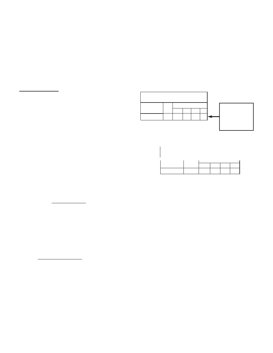
TABLE 3. MAX TRACKING RATE (MIN)
IN RPS
RS
RESOLUTION
10
12
14
16
30k or open* 30 k 1152 288
72
18
5
10
30 k
30k or open*
16
14
12
10
RESOLUTION
RS
RC
TABLE 4. CARRIER FREQUENCY (MAX)
IN KHZ
Depending on the res-
olution, select one of
the values from this
row, for use in convert-
er max tracking rate
formula. (See previous
page for formula.)
*The use of a high quality thin-film resistor will
provide better temperature stability than leaving
open.
The maximum rate capability of the RDC-19220/2S is set by RS.
When RS = 30 kHz it is nominally 1,333,333 counts/second,
which equates to 325 rps (rotations per second). This is the
absolute maximum; it is recommended to only run at < 90% of
this rate (as given in Table 3), therefore the minimum RV will be
limited to 55 kOhms.
相关PDF资料 |
PDF描述 |
|---|---|
| RDC-19224G-202T | SYNCHRO OR RESOLVER TO DIGITAL CONVERTER, PQFP44 |
| RDC-19224G-A03T | SYNCHRO OR RESOLVER TO DIGITAL CONVERTER, PQFP44 |
| RDC-636A-M1R | SYNCHRO OR RESOLVER TO DIGITAL CONVERTER, DMA28 |
| SDC-634A-L3R | SYNCHRO OR RESOLVER TO DIGITAL CONVERTER, DIP27 |
| REC3-0512DR | ECONOLINE - DC/DC - CONVERTER |
相关代理商/技术参数 |
参数描述 |
|---|---|
| RDC-19222S-313T | 制造商:未知厂家 制造商全称:未知厂家 功能描述:Converter |
| RDC19223-101 | 制造商:未知厂家 制造商全称:未知厂家 功能描述:Converter IC |
| RDC-19223-102 | 制造商:未知厂家 制造商全称:未知厂家 功能描述:LVDT/Resolver-to-Digital Converter |
| RDC-19223-103 | 制造商:未知厂家 制造商全称:未知厂家 功能描述:LVDT/Resolver-to-Digital Converter |
| RDC19223-121 | 制造商:未知厂家 制造商全称:未知厂家 功能描述:Converter IC |
发布紧急采购,3分钟左右您将得到回复。