- 您现在的位置:买卖IC网 > PDF目录270737 > RP-21203G1-800 (DATA DEVICE CORP) SPECIALTY ANALOG CIRCUIT, XMA20 PDF资料下载
参数资料
| 型号: | RP-21203G1-800 |
| 厂商: | DATA DEVICE CORP |
| 元件分类: | 模拟信号调理 |
| 英文描述: | SPECIALTY ANALOG CIRCUIT, XMA20 |
| 封装: | PLASTIC, GULLWING LEAD PACKAGE-20 |
| 文件页数: | 16/20页 |
| 文件大小: | 228K |
| 代理商: | RP-21203G1-800 |
5
Data Device Corporation
www.ddc-web.com
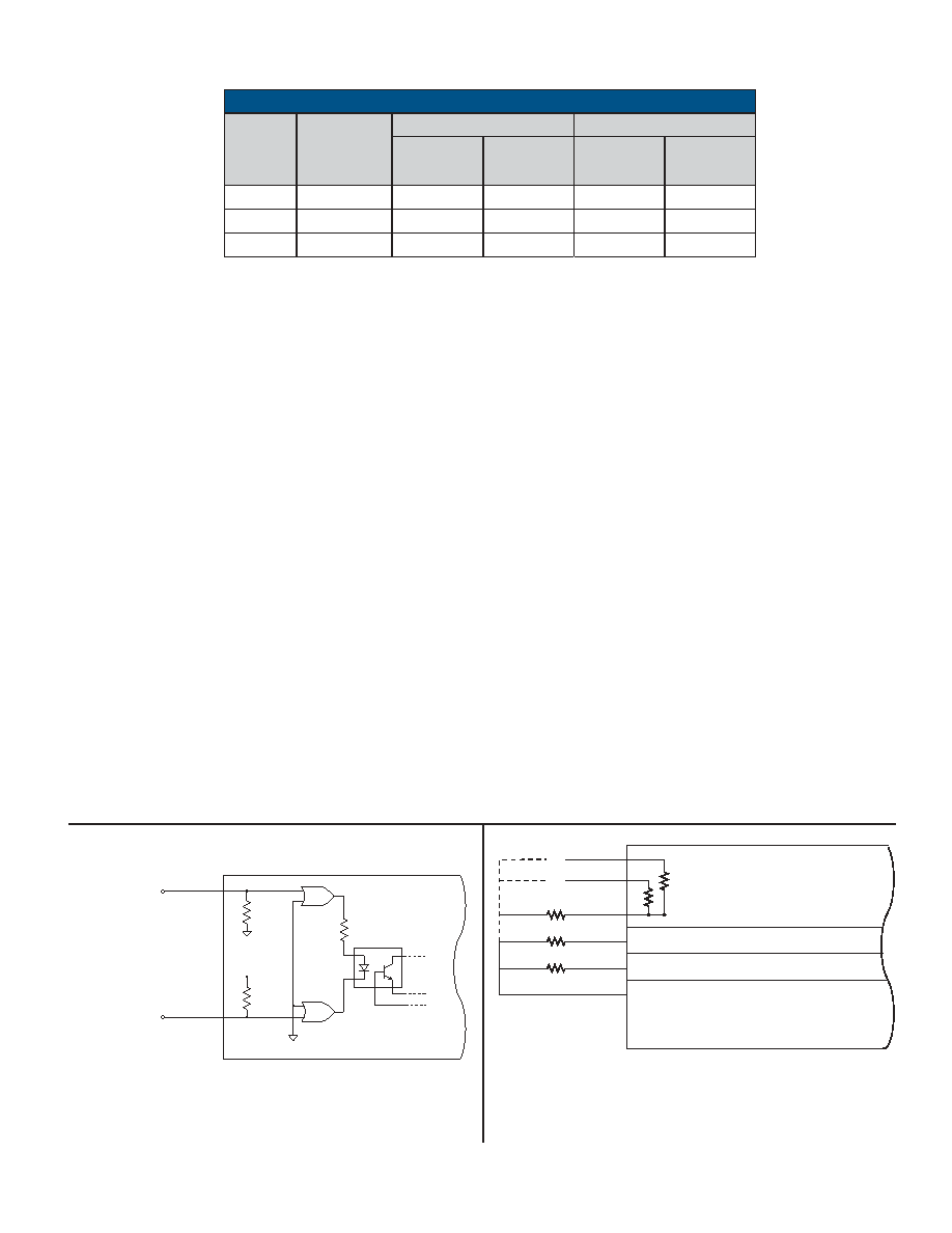
RP-21200
D-02/04-0
Control Command
Lockout Command
BiasGnd
100K
BiasGnd
RP-212XX
R
Vbias
FIGURE 2. RP-212XX SERIES CONTROL/LOCKOUT
FUNCTIONAL SCHEMATIC
RP-212XX
I
3
2
Current Range Programming
Load Detection Programming
Instant Trip Programming
Program Reference
R
1
2
3
Internal Preset Programming Options
FIGURE 3. RP-212XX SERIES PROGRAMMING
CONNECTIONS
in the area between the minimum and maximum curves is
ambiguous; the SSPC may or may not trip.
A hot wire cannot withstand as great an overload as a cool wire.
The
STAR Series of SSPCs incorporate ‘Thermal Memory’ to
protect a wire that is hot from a previous overload.
The Instant Trip Characteristic ranges shown in FIGURE 5 are pro-
grammable as detailed in FIGURE 4. If the overload exceeds the
upper Instant Trip level, the SSPC will trip regardless of the dura-
tion of the overload. The main reason for an Instant Trip level is to
protect the switch from excessive short-term power dissipation but
can be programmed for system considerations, if necessary.
The RP-21200
STAR Series are available in three current
ranges. As shown in TABLE 5, they are programmable over a
three-to-one range. The ranges are: 1 - 3 Amps, 3 - 9 Amps and
8.3 to 25 Amps. TABLE 4 shows the Maximum “on” resistance
and voltage drops over the temperature range.
The rise and fall times of the output voltage are controlled to be
approximately 500S. Fast rise times minimize the power dissi-
pation in the switch during turn-on and turn-off. Slow rise times
minimize EMI, voltage spiking due to line inductance and allow
starting up into higher capacitive loads. The 500S rise and fall
times in the
STAR Series represent a compromise. While the
switch can handle the power dissipation during occasional
changes of state, rapidly switching the SSPC on and off will lead
to overheating. These SSPCs should not be cycled at greater
than a 30ms rate.
To control the rise and fall time, the Slew Control Input must be
returned to Chassis Ground. The load return is the ideal Chassis
Ground; the Chassis Ground can also be used as a ground but,
if there is noise between Chassis Ground and load return, some
of this noise may appear on the output. An alternative Chassis
Ground is the Power In but, if the Power In is turned on abruptly,
such as through a switch or contactor, the output may exhibit a
small transient although the SSPC is commanded off.
MIN. RATED CURRENT
MAX. RATED CURRENT
PART
NUMBER
“ON”
RESISTANCE
(OHMS)
VOLTAGE
DROP
(V)
POWER
DISSIPATION
(W)
VOLTAGE
DROP
(V)
POWER
DISSIPATION
(W)
RP-21203
0.100
0.1
0.25
0.3
1.05
RP-21209
0.033
0.1
0.45
0.3
2.85
RP-21225
0.012
0.1
0.98
0.3
7.65
TABLE 4. POWER DISSIPATION
TABLE 4 notes:
1. Values shown are maximum over the case temperature range of -55°C to +100°C; typical values at
25°C are typically 67% of the maximums shown above.
2. Voltage drop is approximately 0.6% per °C improved below the100°C limit.
3. Power Dissipation data includes 150 mW contribution of VBIAS, but doesn’t include the analog current
monitor (see TABLE 3). “F1” is another 45 mA maximum.
相关PDF资料 |
PDF描述 |
|---|---|
| RP-21010D0-150Y | SPECIALTY ANALOG CIRCUIT, DMA10 |
| R5106N341C-TR-F | 1-CHANNEL POWER SUPPLY MANAGEMENT CKT, PDSO6 |
| R3114N331C-TR-F | 1-CHANNEL POWER SUPPLY SUPPORT CKT, PDSO5 |
| R3114N371A-TR-F | 1-CHANNEL POWER SUPPLY SUPPORT CKT, PDSO5 |
| R5109G421A-TR-FE | 1-CHANNEL POWER SUPPLY MANAGEMENT CKT, PDSO8 |
相关代理商/技术参数 |
参数描述 |
|---|---|
| RP-21203XX | 制造商:未知厂家 制造商全称:未知厂家 功能描述:POWER CONTROLLERS|Rad Hard Hybrid. True I2t Protection |
| RP-21209XX | 制造商:未知厂家 制造商全称:未知厂家 功能描述:POWER CONTROLLERS|STAR Series Programmable. Low Cost. EMI Tolerant Module |
| RP-21225XX | 制造商:未知厂家 制造商全称:未知厂家 功能描述:POWER CONTROLLERS|STAR Series Programmable. Low Cost. EMI Tolerant Module |
| RP220-10-4.7-QD | 制造商:RADIUS POWER 功能描述:EMI POWER LINE FILTER |
| RP220-16-4.7-QD | 制造商:RADIUS POWER 功能描述:EMI POWER LINE FILTER |
发布紧急采购,3分钟左右您将得到回复。