- 您现在的位置:买卖IC网 > PDF目录98069 > S1D13A05B00B 320 X 320 PIXELS CRT OR FLAT PNL GRPH DSPL CTLR, PBGA121 PDF资料下载
参数资料
| 型号: | S1D13A05B00B |
| 元件分类: | 显示控制器 |
| 英文描述: | 320 X 320 PIXELS CRT OR FLAT PNL GRPH DSPL CTLR, PBGA121 |
| 封装: | PLASTIC, FBGA-121 |
| 文件页数: | 28/190页 |
| 文件大小: | 2285K |
| 代理商: | S1D13A05B00B |
第1页第2页第3页第4页第5页第6页第7页第8页第9页第10页第11页第12页第13页第14页第15页第16页第17页第18页第19页第20页第21页第22页第23页第24页第25页第26页第27页当前第28页第29页第30页第31页第32页第33页第34页第35页第36页第37页第38页第39页第40页第41页第42页第43页第44页第45页第46页第47页第48页第49页第50页第51页第52页第53页第54页第55页第56页第57页第58页第59页第60页第61页第62页第63页第64页第65页第66页第67页第68页第69页第70页第71页第72页第73页第74页第75页第76页第77页第78页第79页第80页第81页第82页第83页第84页第85页第86页第87页第88页第89页第90页第91页第92页第93页第94页第95页第96页第97页第98页第99页第100页第101页第102页第103页第104页第105页第106页第107页第108页第109页第110页第111页第112页第113页第114页第115页第116页第117页第118页第119页第120页第121页第122页第123页第124页第125页第126页第127页第128页第129页第130页第131页第132页第133页第134页第135页第136页第137页第138页第139页第140页第141页第142页第143页第144页第145页第146页第147页第148页第149页第150页第151页第152页第153页第154页第155页第156页第157页第158页第159页第160页第161页第162页第163页第164页第165页第166页第167页第168页第169页第170页第171页第172页第173页第174页第175页第176页第177页第178页第179页第180页第181页第182页第183页第184页第185页第186页第187页第188页第189页第190页
Epson Research and Development
Page 123
Vancouver Design Center
Hardware Functional Specification
S1D13A05
Issue Date: 02/07/02
X40A-A-001-02
8.3.7 Miscellaneous Registers
The S1D13A05 GPIO pins default to inputs, however they can be individually configured
to outputs or inputs using the GPIO[7:0] Config bits (bits 23-16). If a GPIO pin is
configured as an input, the input functionality must be enabled using the corresponding
GPIO[7:0] Input Enable pin (see bits 31-24). Once the GPIO pin has been configured, it can
be controlled/read using the GPIO[7:0] Control/Status bits (bits 7-0). See the individual bit
descriptions for further details.
Some GPIOs must be configured as outputs after every RESET for use with some extended
panel types (i.e. Sharp HR-TFT, Casio TFT, etc). See Table 4-9: “LCD Interface Pin
Mapping,” on page 36 and the individual bit descriptions for bits 7-0 for specific infor-
mation on each GPIO pin.
bits 31-24
GPIO[7:0] Input Enable bits
These bits individually enable the input function for each GPIO pin (GPIO[7:0]). After
power-on/reset, each bit must be set to a 1 to enable the input function of each GPIO pin
(default is 0 except for GPIO5 which is 1). If the GPIO pin is configured as an output the
GPIO[7:0] Input Enable bit has no effect.
Note
At power-on/reset, the GPIO5 Input Enable bit (bit 29) defaults to 1.
bits 23-16
GPIO[7:0] IO Configuration
At power-on/reset, the GPIO[7:0] pins default to inputs. These bits individually configure
each GPIO pin as either an output or input.
When these bits = 0, the associated GPIO pin is configured as an input.
When these bits = 1, the associated GPIO pin is configured as an output.
This may be required for some extended panel types (i.e. Sharp HR-TFT, Casio TFT, etc.)
or USB. See Table 4-9: “LCD Interface Pin Mapping,” on page 36 and the individual bit
descriptions for bits 7-0 for specific information on each GPIO pin.
Note
If a GPIO pin is configured as an input, the input function of the GPIO pin must be en-
abled using the corresponding GPIOx Input Enable bit (bits 31-24) before the input con-
figuration takes effect.
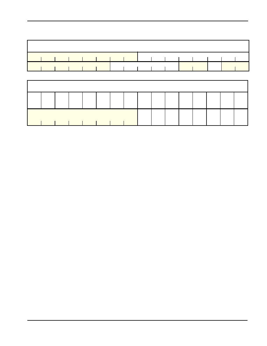
Reserved
REG[60h]
Default = 00000000h
Read/Write
n/a
Reserved
31
30
29
28
27
26
25
24
23
22
21
20
19
18
17
16
n/a
Reserved
n/a
Reserved
n/a
15
14
13
12
11
10
987
65
4
32
1
0
GPIO Status and Control Register
REG[64h]
Default = 20000000h
Read/Write
GPIO7
Input
Enable
GPIO6
Input
Enable
GPIO5
Input
Enable
GPIO4
Input
Enable
GPIO3
Input
Enable
GPIO2
Input
Enable
GPIO1
Input
Enable
GPIO0
Input
Enable
GPIO7
Config
GPIO6
Config
GPIO5
Config
GPIO4
Config
GPIO3
Config
GPIO2
Config
GPIO1
Config
GPIO0
Config
31
30
29
28
27
26
25
24
23
22
21
20
19
18
17
16
n/a
GPIO7
Control/
Status
GPIO6
Control/
Status
GPIO5
Control/
Status
GPIO4
Control/
Status
GPIO3
Control/
Status
GPIO2
Control/
Status
GPIO1
Control/
Status
GPIO0
Control/
Status
15
14
13
12
11
10
9
87
654321
0
相关PDF资料 |
PDF描述 |
|---|---|
| S1D13A05F00A100 | 320 X 320 PIXELS CRT OR FLAT PNL GRPH DSPL CTLR, PBGA121 |
| S1R72005F00A300 | UNIVERSAL SERIAL BUS CONTROLLER, PQFP64 |
| S1R72105F00A000 | SCSI BUS CONTROLLER, PQFP100 |
| S1R72803F00A100 | 1 CHANNEL(S), 400M bps, SERIAL COMM CONTROLLER, PQFP100 |
| S1R72C05B08 | UNIVERSAL SERIAL BUS CONTROLLER, PBGA121 |
相关代理商/技术参数 |
参数描述 |
|---|---|
| S1D13A05B00B200 | 功能描述:LCD 驱动器 (QVGA) 320x240 LCD Controller @ 16bpp RoHS:否 制造商:Maxim Integrated 数位数量:4.5 片段数量:30 最大时钟频率:19 KHz 工作电源电压:3 V to 3.6 V 最大工作温度:+ 85 C 最小工作温度:- 20 C 封装 / 箱体:PDIP-40 封装:Tube |
| S1D13A05F00A100 | 功能描述:显示驱动器和控制器 (QVGA) 320x240 LCD Controller @ 16bpp RoHS:否 制造商:Panasonic Electronic Components 工作电源电压:2.7 V to 5.5 V 最大工作温度: 安装风格:SMD/SMT 封装 / 箱体:QFN-44 封装:Reel |
| S1D13A05F00A200 | 制造商:Epson Electronics America Inc 功能描述:LCD DRVR 3V/3.3V/5V 80-Pin TQFP |
| S1D-13-F | 功能描述:整流器 200V 1A RoHS:否 制造商:Vishay Semiconductors 产品:Standard Recovery Rectifiers 配置: 反向电压:100 V 正向电压下降: 恢复时间:1.2 us 正向连续电流:2 A 最大浪涌电流:35 A 反向电流 IR:5 uA 安装风格:SMD/SMT 封装 / 箱体:DO-221AC 封装:Reel |
| S1D13T03F10A100 | 制造商:Epson Electronics America Inc 功能描述:IC EPD CONTROLLER 64TQFP13 制造商:Epson Electronics America Inc 功能描述:EPD Controller Timing control |
发布紧急采购,3分钟左右您将得到回复。