参数资料
| 型号: | SCC2681AC1N40,112 |
| 厂商: | NXP Semiconductors |
| 文件页数: | 8/29页 |
| 文件大小: | 0K |
| 描述: | IC UART DUAL 40-DIP |
| 产品培训模块: | Stand-Alone UARTs |
| 标准包装: | 9 |
| 特点: | 故障启动位检测 |
| 通道数: | 2,DUART |
| FIFO's: | 3 位 |
| 电源电压: | 5V |
| 带并行端口: | 是 |
| 带自动流量控制功能: | 是 |
| 带故障启动位检测功能: | 是 |
| 带CMOS: | 是 |
| 安装类型: | 通孔 |
| 封装/外壳: | 40-DIP(0.600",15.24mm) |
| 供应商设备封装: | 40-DIP |
| 包装: | 管件 |
| 其它名称: | 568-3525-5 935274523112 SCC2681AC1N40 |
第1页第2页第3页第4页第5页第6页第7页当前第8页第9页第10页第11页第12页第13页第14页第15页第16页第17页第18页第19页第20页第21页第22页第23页第24页第25页第26页第27页第28页第29页
Philips Semiconductors
Product data
SCC2681
Dual asynchronous receiver/transmitter (DUART)
2004 Apr 06
16
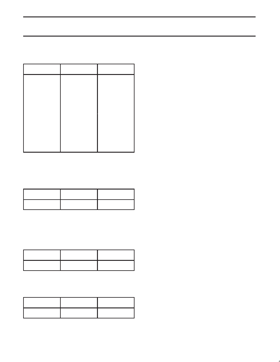
CSRA[7:4] – Channel A Receiver Clock Select
This field selects the baud rate clock for the Channel A receiver as
follows (X1 rate at 3.6864 MHz):
CSRA[7:4]
ACR[7] = 0
Baud Rate
ACR[7] = 1
0000
50
75
0001
110
0010
134.5
0011
200
150
0100
300
0101
600
0110
1,200
0111
1,050
2,000
1000
2,400
1001
4,800
1010
7,200
1,800
1011
9,600
1100
38.4k
19.2k
1101
Timer
1110
IP4–16
×
IP4–16
×
1111
IP4–1
×
IP4–1
×
(See also Table 5 for other rates to 115.2 kHz)
Rates will change in direct proportion to X1 at 3.6864 MHz.
The receiver clock is always a 16
× clock except for CSRA[7] = 1111.
CSRA[3:0] – Channel A Transmitter Clock Select
This field selects the baud rate clock for the Channel A transmitter.
The field definition is as per CSR[7:4] except as follows:
CSRA[3:0]
ACR[7] = 0
Baud Rate
ACR[7] = 1
1110
1111
IP3–16
×
IP3–1
×
IP3–16
×
IP3–1
×
The transmitter clock is always a 16
× clock except for
CSR[3:0] = 1111.
CSRB – Channel B Clock Select Register
CSRB[7:4] – Channel B Receiver Clock Select
This field selects the baud rate clock for the Channel B receiver. The
field definition is as per CSRA[7:4] except as follows:
CSRB[7:4]
ACR[7] = 0
Baud Rate
ACR[7] = 1
1110
1111
IP6–16
×
IP6–1
×
IP6–16
×
IP6–1
×
The receiver clock is always a 16
× clock except for CSRB[7:4] = 1111.
CSRB[3:0] – Channel B Transmitter Clock Select
This field selects the baud rate clock for the Channel B transmitter.
The field definition is as per CSRA[7:4] except as follows:
CSRB[3:0]
ACR[7] = 0
Baud Rate
ACR[7] = 1
1110
1111
IP5–16
×
IP5–1
×
IP5–16
×
IP5–1
×
The transmitter clock is always a 16
× clock except for
CSRB[3:0] = 1111.
CRA – Channel A Command Register
CRA is a register used to supply commands to Channel A. Multiple
commands can be specified in a single write to CRA as long as the
commands are non-conflicting, e.g., the ‘enable transmitter’ and
‘reset transmitter’ commands cannot be specified in a single
command word.
CRA[7] – Not Used
Must be set to zero.
CRA[6:4] – Channel A Miscellaneous Command
The encoded value of this field may be used to specify a single
command as follows:
CRA[6:4] – COMMAND
000
No command.
001
Reset MR pointer. Causes the Channel A MR pointer to point
to MR1.
010
Reset receiver. Resets the Channel A receiver as if a hard-
ware reset had been applied. The receiver is disabled and the
FIFO is flushed.
011
Reset transmitter. Resets the Channel A transmitter as if a
hardware reset had been applied.
100
Reset error status. Clears the Channel A Received Break,
Parity Error, and Overrun Error bits in the status register
(SRA[7:4]). Used in character mode to clear OE status (al-
though RB, PE and FE bits will also be cleared) and in block
mode to clear all error status after a block of data has been
received.
101
Reset Channel A break change interrupt. Causes the Chan-
nel A break detect change bit in the interrupt status register
(ISR[2]) to be cleared to zero.
110
Start break. Forces the TxDA output LOW (spacing). If the
transmitter is empty the start of the break condition will be
delayed up to two bit times. If the transmitter is active the
break begins when transmission of the character is com-
pleted. If a character is in the THR, the start of the break will
be delayed until that character, or any other loaded subse-
quently are transmitted. The transmitter must be enabled for
this command to be accepted.
111
Stop break. The TxDA line will go HIGH (marking) within two
bit times. TxDA will remain HIGH for one bit time before the
next character, if any, is transmitted.
CRA[3] – Disable Channel A Transmitter
This command terminates transmitter operation and reset the
TxDRY and TxEMT status bits. However, if a character is being
transmitted or if a character is in the THR when the transmitter is
disabled, the transmission of the character(s) is completed before
assuming the inactive state. A disable transmitter cannot be loaded.
CRA[2] – Enable Channel A Transmitter
Enables operation of the Channel A transmitter. The TxRDY status
bit will be asserted.
CRA[1] – Disable Channel A Receiver
This command terminates operation of the receiver immediately – a
character being received will be lost. The command has no effect on
the receiver status bits or any other control registers. If the special
multidrop mode is programmed, the receiver operates even if it is
disabled. See Operation section.
CRA[0] – Enable Channel A Receiver
Enables operation of the Channel A receiver. If not in the special
wake up mode, this also forces the receiver into the search for
start-bit state.
Note: Performing disable and enable at the same time results in
disable.
相关PDF资料 |
PDF描述 |
|---|---|
| SC16IS760IBS,151 | IC UART I2C/SPI 24-HVQFN |
| XR16C854CJ-F | IC UART FIFO 128B QUAD 68PLCC |
| XR82C684CJ/44-F | IC UART CMOS QUAD 44PLCC |
| XR16C2850IJ-F | IC UART FIFO 128B 44PLCC |
| ST16C554DIJ68-F | IC UART FIFO 16B QUAD 68PLCC |
相关代理商/技术参数 |
参数描述 |
|---|---|
| SCC2681AE1A44 | 功能描述:UART 接口集成电路 RPLACMNT FOR SCN2681 RoHS:否 制造商:Texas Instruments 通道数量:2 数据速率:3 Mbps 电源电压-最大:3.6 V 电源电压-最小:2.7 V 电源电流:20 mA 最大工作温度:+ 85 C 最小工作温度:- 40 C 封装 / 箱体:LQFP-48 封装:Reel |
| SCC2681AE1A44,512 | 功能描述:UART 接口集成电路 RPLACMNT FOR SCN2681 RoHS:否 制造商:Texas Instruments 通道数量:2 数据速率:3 Mbps 电源电压-最大:3.6 V 电源电压-最小:2.7 V 电源电流:20 mA 最大工作温度:+ 85 C 最小工作温度:- 40 C 封装 / 箱体:LQFP-48 封装:Reel |
| SCC2681AE1A44,518 | 功能描述:UART 接口集成电路 RPLACMNT FOR SCN2681 RoHS:否 制造商:Texas Instruments 通道数量:2 数据速率:3 Mbps 电源电压-最大:3.6 V 电源电压-最小:2.7 V 电源电流:20 mA 最大工作温度:+ 85 C 最小工作温度:- 40 C 封装 / 箱体:LQFP-48 封装:Reel |
| SCC2681AE1A44,529 | 功能描述:UART 接口集成电路 RPLACMNT FOR SCN2681 RoHS:否 制造商:Texas Instruments 通道数量:2 数据速率:3 Mbps 电源电压-最大:3.6 V 电源电压-最小:2.7 V 电源电流:20 mA 最大工作温度:+ 85 C 最小工作温度:- 40 C 封装 / 箱体:LQFP-48 封装:Reel |
| SCC2681AE1A44512 | 制造商:Rochester Electronics LLC 功能描述: 制造商:NXP Semiconductors 功能描述: |
发布紧急采购,3分钟左右您将得到回复。