- 您现在的位置:买卖IC网 > PDF目录11822 > SCC2692AC1N28,129 (NXP Semiconductors)IC DUART 28-DIP PDF资料下载
参数资料
| 型号: | SCC2692AC1N28,129 |
| 厂商: | NXP Semiconductors |
| 文件页数: | 10/30页 |
| 文件大小: | 0K |
| 描述: | IC DUART 28-DIP |
| 标准包装: | 13 |
| 特点: | 故障启动位检测 |
| 通道数: | 2,DUART |
| FIFO's: | 3 位 |
| 电源电压: | 5V |
| 带并行端口: | 是 |
| 带自动流量控制功能: | 是 |
| 带故障启动位检测功能: | 是 |
| 带CMOS: | 是 |
| 安装类型: | 通孔 |
| 封装/外壳: | 28-DIP(0.600",15.24mm) |
| 供应商设备封装: | 28-DIP |
| 包装: | 管件 |
| 其它名称: | 933981720129 SCC2692AC1N28-S SCC2692AC1N28-S-ND |
第1页第2页第3页第4页第5页第6页第7页第8页第9页当前第10页第11页第12页第13页第14页第15页第16页第17页第18页第19页第20页第21页第22页第23页第24页第25页第26页第27页第28页第29页第30页
Philips Semiconductors
Product specification
SCC2692
Dual asynchronous receiver/transmitter (DUART)
1998 Sep 04
18
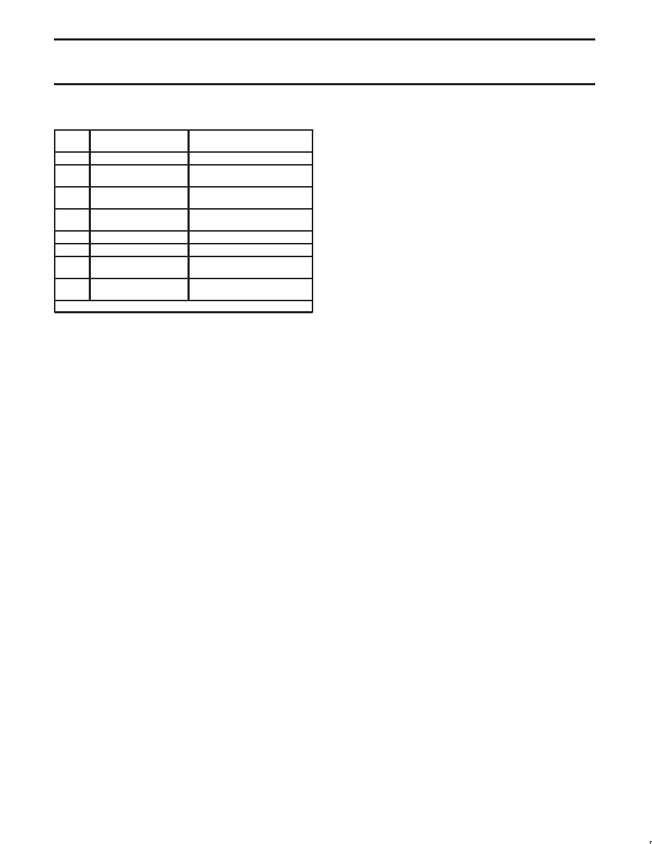
Table 5.
ACR 6:4 Field Definition
ACR
6:4
MODE
CLOCK SOURCE
000
Counter
External (IP2)
001
Counter
TxCA – 1X clock of Channel A
transmitter
010
Counter
TxCB – 1X clock of Channel B
transmitter
011
Counter
Crystal or external (X1/CLK)
divided by 16
100
Timer (square wave)
External (IP2)
101
Timer (square wave)
External (IP2) divided by 16
110
Timer (square wave)
Crystal or external clock
(X1/CLK)
111
Timer (square wave)
Crystal or IP2 clock (X1/CLK)
divided by 16
NOTE: Timer mode generates a squarewave.
IPCR – Input Port Change Register
IPCR[7:4] – IP3, IP2, IP1, IP0 Change-of-State
These bits are set when a change-of-state, as defined in the input
port section of this data sheet, occurs at the respective input pins.
They are cleared when the IPCR is read by the CPU. A read of the
IPCR also clears ISR[7], the input change bit in the interrupt status
register. The setting of these bits can be programmed to generate
an interrupt to the CPU.
IPCR[3:0] – IP3, IP2, IP1, IP0 Change-of-State
These bits provide the current state of the respective inputs. The
information is unlatched and reflects the state of the input pins at the
time the IPCR is read.
ISR – Interrupt Status Register
This register provides the status of all potential interrupt sources.
The contents of this register are masked by the Interrupt Mask
Register (IMR). If a bit in the ISR is a ‘1’ and the corresponding bit in
the IMR is also a ‘1’, the INTRN output will be asserted (Low). If the
corresponding bit in the IMR is a zero, the state of the bit in the ISR
has no effect on the INTRN output. Note that the IMR does not mask
the reading of the ISR – the true status will be provided regardless
of the contents of the IMR. The contents of this register are
initialized to 0016 when the DUART is reset.
ISR[7] – Input Port Change Status
This bit is a ‘1’ when a change-of-state has occurred at the IP0, IP1,
IP2, or IP3 inputs and that event has been selected to cause an
interrupt by the programming of ACR[3:0]. The bit is cleared when
the CPU reads the IPCR.
ISR[6] – Channel B Change In Break
This bit, when set, indicates that the Channel B receiver has
detected the beginning or the end of a received break. It is reset
when the CPU issues a Channel B ‘reset break change interrupt’
command.
ISR[5] – Channel B Receiver Ready or FIFO Full
The function of this bit is programmed by MR1B[6]. If programmed
as receiver ready, it indicates that a character has been received in
Channel B and is waiting in the FIFO to be read by the CPU. It is set
when the character is transferred from the receive shift register to
the FIFO and reset when the CPU reads the RHR. If after this read
there are more characters still in the FIFO the bit will be set again
after the FIFO is ‘popped’. If programmed as FIFO full, it is set when
a character is transferred from the receive holding register to the
receive FIFO and the transfer caused the Channel B FIFO to
become full; i.e., all three FIFO positions are occupied. It is reset
when the CPU reads the RHR. If a character is waiting in the
receive shift register because the FIFO is full, the bit will be set
again when the waiting character is loaded into the FIFO.
ISR[4] – Channel B Transmitter Ready
This bit is a duplicate of TxRDYB (SRB[2]).
ISR[3] – Counter Ready.
In the counter mode, this bit is set when the counter reaches
terminal count and is reset when the counter is stopped by a stop
counter command.
In the timer mode, this bit is set once each cycle of the generated
square wave (every other time that the counter/timer reaches zero
count). The bit is reset by a stop counter command. The command,
however, does not stop the counter/timer.
In the time-out mode, the “Disable Time-out Mode” command (CR
x’C0) must be used.
ISR[2] – Channel A Change in Break
This bit, when set, indicates that the Channel A receiver has
detected the beginning or the end of a received break. It is reset
when the CPU issues a Channel A ‘reset break change interrupt’
command.
ISR[1] – Channel A Receiver Ready Or FIFO Full
The function of this bit is programmed by MR1A[6]. If programmed
as receiver ready, it indicates that a character has been received in
Channel A and is waiting in the FIFO to be read by the CPU. It is set
when the character is transferred from the receive shift register to
the FIFO and reset when the CPU reads the RHR. If after this read
there are more characters still in the FIFO the bit will be set again
after the FIFO is ‘popped’. If programmed as FIFO full, it is set
when a character is transferred from the receive holding register to
the receive FIFO and the transfer caused the Channel A FIFO to
become full; i.e., all three FIFO positions are occupied. It is reset
when the CPU reads the RHR. If a character is waiting in the
receive shift register because the FIFO is full, the bit will be set
again when the ISR[0] and IMR waiting character is loaded into the
FIFO.
ISR[0] – Channel A Transmitter Ready
This bit is a duplicate of TxRDYA (SRA[2]).
IMR – Interrupt Mask Register
The programming of this register selects which bits in the ISR
causes an interrupt output. If a bit in the ISR is a ‘1’ and the
corresponding bit in the IMR is also a ‘1’ the INTRN output will be
asserted. If the corresponding bit in the IMR is a zero, the state of
the bit in the ISR has no effect on the INTRN output. Note that the
IMR does not mask the programmable interrupt outputs OP3-OP7 or
the reading of the ISR.
CTUR and CTLR – Counter/Timer Registers
The CTUR and CTLR hold the eight MSBs and eight LSBs,
respectively, of the value to be used by the counter/timer in either
the counter or timer modes of operation. The minimum value which
may be loaded into the CTUR/CTLR registers is H‘0002’. Note that
these registers are write-only and cannot be read by the CPU.
In the timer (programmable divider) mode, the C/T generates a
square wave with a period of twice the value (in clock periods) of the
CTUR and CTLR. The waveform so generated is often used for a
相关PDF资料 |
PDF描述 |
|---|---|
| SCC2692AC1A44,529 | IC DUART SOT187-2 |
| VI-B5D-IY | CONVERTER MOD DC/DC 85V 50W |
| SC26C92C1A,529 | IC DUART SOT187-2 |
| SC16C554BIBM,128 | IC UART QUAD SOT414-1 |
| SCC68692E1A44,518 | IC DUART 44PLCC |
相关代理商/技术参数 |
参数描述 |
|---|---|
| SCC2692AC1N28-S | 功能描述:UART 接口集成电路 5V INDSTRL UART 2 C RoHS:否 制造商:Texas Instruments 通道数量:2 数据速率:3 Mbps 电源电压-最大:3.6 V 电源电压-最小:2.7 V 电源电流:20 mA 最大工作温度:+ 85 C 最小工作温度:- 40 C 封装 / 箱体:LQFP-48 封装:Reel |
| SCC2692AC1N40 | 制造商:NXP Semiconductors 功能描述:IC DUART 2692 DIP40 制造商:NXP Semiconductors 功能描述:IC, DUART, 2692, DIP40 制造商:NXP Semiconductors 功能描述:IC, DUAL UART, FIFO, 115KBAUD 5.5V DIP40; No. of Channels:2; Data Rate:1Mbps; Supply Voltage Min:4.5V; Supply Voltage Max:5.5V; Digital IC Case Style:DIP; No. of Pins:40; Operating Temperature Min:0C; Operating Temperature Max:70C ;RoHS Compliant: Yes |
| SCC2692AC1N40,602 | 功能描述:UART 接口集成电路 2CH. 5V IND. UART RoHS:否 制造商:Texas Instruments 通道数量:2 数据速率:3 Mbps 电源电压-最大:3.6 V 电源电压-最小:2.7 V 电源电流:20 mA 最大工作温度:+ 85 C 最小工作温度:- 40 C 封装 / 箱体:LQFP-48 封装:Reel |
| SCC2692AC1N40602 | 制造商:NXP Semiconductors 功能描述:IC DUAL UART FIFO 1MBPS 5.5V DIP-40 |
| SCC2692AE1A44 | 功能描述:UART 接口集成电路 5V INDSTRL UART 2 C RoHS:否 制造商:Texas Instruments 通道数量:2 数据速率:3 Mbps 电源电压-最大:3.6 V 电源电压-最小:2.7 V 电源电流:20 mA 最大工作温度:+ 85 C 最小工作温度:- 40 C 封装 / 箱体:LQFP-48 封装:Reel |
发布紧急采购,3分钟左右您将得到回复。