- 您现在的位置:买卖IC网 > Datasheet目录251 > SFCF64GBH2BU4TO-I-NU-517-STD (Swissbit NA Inc)FLASH SLC UDMA/MDMA/PIO 64GB Datasheet资料下载
参数资料
| 型号: | SFCF64GBH2BU4TO-I-NU-517-STD |
| 厂商: | Swissbit NA Inc |
| 文件页数: | 14/102页 |
| 文件大小: | 0K |
| 描述: | FLASH SLC UDMA/MDMA/PIO 64GB |
| 标准包装: | 1 |
| 系列: | C-440 |
| 存储容量: | 64GB |
| 存储器类型: | CompactFlash? |
| 其它名称: | 1052-1090 |
第1页第2页第3页第4页第5页第6页第7页第8页第9页第10页第11页第12页第13页当前第14页第15页第16页第17页第18页第19页第20页第21页第22页第23页第24页第25页第26页第27页第28页第29页第30页第31页第32页第33页第34页第35页第36页第37页第38页第39页第40页第41页第42页第43页第44页第45页第46页第47页第48页第49页第50页第51页第52页第53页第54页第55页第56页第57页第58页第59页第60页第61页第62页第63页第64页第65页第66页第67页第68页第69页第70页第71页第72页第73页第74页第75页第76页第77页第78页第79页第80页第81页第82页第83页第84页第85页第86页第87页第88页第89页第90页第91页第92页第93页第94页第95页第96页第97页第98页第99页第100页第101页第102页
�� �
�
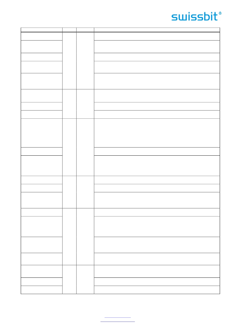
�Signal� Name�
�–� IORD�
�(PC� Card� Memory� Mode)�
�–� IORD�
�(PC� Card� I/O� Mode)�
�–� IORD�
�(True� IDE� Mode)�
�-HDMARDY�
�(True� IDE� Mode� –� In� Ultra�
�DMA� Protocol� DMA� Read)�
�HSTROBE�
�(True� IDE� Mode� –� In� Ultra�
�DMA� Protocol� DMA�
�Write)�
�–� CD1,� –� CD2�
�(PC� Card� Memory� Mode)�
�–� CD1,� –� CD2�
�(PC� Card� I/O� Mode)�
�–� CD1,� –� CD2�
�(True� IDE� Mode)�
�Dir.�
�I�
�O�
�Pin�
�34�
�26,� 25�
�Description�
�This� signal� is� not� used� in� this� mode.�
�This� is� an� I/O� Read� strobe� generated� by� the� host.� This� signal� gates� I/O� data� onto�
�the� bus� from� the� CompactFlash� TM� Storage� Card� when� the� card� is� configured� to�
�use� the� I/O� interface.�
�In� True� IDE� Mode,� while� Ultra� DMA� mode� is� not� active,� this� signal� has� the� same�
�function� as� in� PC� Card� I/O� Mode.�
�In� True� IDE� Mode� when� Ultra� DMA� mode� DMA� Read� is� active,� this� signal� is�
�asserted� by� the� host� to� indicate� that� the� host� is� read� to� receive� Ultra� DMA� data-�
�in� bursts.� The� host� may� negate� -HDMARDY� to� pause� an� Ultra� DMA� transfer.�
�In� True� IDE� Mode� when� Ultra� DMA� mode� DMA� Write� is� active,� this� signal� is� the�
�data� out� strobe� generated� by� the� host.� Both� the� rising� and� falling� edge� of�
�HSTROBE� cause� data� to� be� latched� by� the� device.� The� host� may� stop� generating�
�HSTROBE� edges� to� pause� an� Ultra� DMA� data-out� burst.�
�These� Card� Detect� pins� are� connected� to� ground� on� the� CompactFlash� TM� Storage�
�Card.� They� are� used� by� the� host� to� determine� that� the� CompactFlash� TM� Storage�
�Card� or� is� fully� inserted� into� its� socket.�
�This� signal� is� the� same� for� all� modes.�
�This� signal� is� the� same� for� all� modes.�
�These� input� signals� are� used� both� to� select� the� card� and� to� indicate� to� the� card�
�whether� a� byte� or� a� word� operation� is� being� performed.� –� CE2� always� accesses�
�–� CE1,� –� CE2�
�(PC� Card� Memory� Mode)�
�the� odd� byte� of� the� word.�
�-CE1� accesses� the� even� byte� or� the� Odd� byte� of� the� word� depending� on� A0� and�
�–� CE2.� A� multiplexing� scheme� based� on� A0,� -CE1,� -CE2� allows� 8� bit� hosts� to�
�access� all� data� on� D0-D7.� See� Table� 31� ,� Table� 38� ,� Table� 39� ,� Table� 40� ,� and�
�–� CE1,� –� CE2�
�(PC� Card� I/O� Mode)�
�I�
�7,� 32�
��This� signal� is� the� same� as� the� PC� Card� Memory� Mode� signal.�
�In� the� True� IDE� Mode,� -CS0� is� the� chip� select� for� the� task� file� registers� while� –� CS1�
�–� CS0,� –� CS1�
�(True� IDE� Mode)�
�–� CSEL�
�(PC� Card� Memory� Mode)�
�–� CSEL�
�is� used� to� select� the� Alternate� Status� Register� and� the� Device� Control� Register.�
�While� –� DMACK� is� asserted,� -CS0� and� –� CS1� shall� be� held� negated� and� the� width�
�of� the� transfers� shall� be� 16� bits.�
�This� signal� is� not� used� for� this� mode,� but� should� be� connected� by� the� host� to� PC�
�Card� A25� or� grounded� by� the� host.�
�This� signal� is� not� used� for� this� mode,� but� should� be� connected� by� the� host� to� PC�
�(PC� Card� I/O� Mode)�
�–� CSEL�
�(True� IDE� Mode)�
�I�
�39�
�Card� A25� or� grounded� by� the� host.�
�This� internally� pulled� up� signal� is� used� to� configure� this� device� as� a� Master� or� a�
�Slave� when� configured� in� the� True� IDE� Mode.�
�When� this� pin� is� grounded,� this� device� is� configured� as� a� Master.�
�When� the� pin� is� open,� this� device� is� configured� as� a� Slave.�
�–� IOWR�
�(PC� Card� Memory� Mode)�
�–� IOWR�
�(PC� Card� I/O� Mode)�
�This� signal� is� not� used� in� this� mode.�
�The� I/O� Write� strobe� pulse� is� used� to� clock� I/O� data� on� the� Card� Data� bus� into� the�
�CompactFlash� TM� Storage� Card� controller� registers� when� the� CompactFlash� TM�
�Storage� Card� is� configured� to� use� the� I/O� interface.�
�The� clocking� shall� occur� on� the� negative� to� positive� edge� of� the� signal� (trailing�
�-IOWR�
�(True� IDE� Mode� –� Except�
�Ultra� DMA� Protocol�
�Active)�
�STOP�
�(True� IDE� Mode� –� Ultra�
�DMA� Protocol� Active)�
�–� OE�
�(PC� Card� Memory� Mode)�
�–� OE�
�(PC� Card� I/O� Mode)�
�–� ATASEL�
�(True� IDE� Mode)�
�I�
�I�
�35�
�9�
�edge).�
�In� True� IDE� Mode,� while� Ultra� DMA� mode� protocol� is� not� active,� this� signal� has�
�the� same� function� as� in� PC� Card� I/O� Mode.�
�When� Ultra� DMA� mode� protocol� is� supported,� this� signal� must� be� negated�
�before� entering� Ultra� DMA� mode� protocol.�
�In� True� IDE� Mode,� while� Ultra� DMA� mode� protocol� is� active,� the� assertion� of� this�
�signal� causes� the� termination� of� the� Ultra� DMA� burst.�
�This� is� an� Output� Enable� strobe� generated� by� the� host� interface.�
�It� is� used� to� read� data� from� the� CompactFlash� TM� Storage� in� Memory� Mode� and� to�
�read� the� CIS� and� configuration� registers.�
�In� PC� Card� I/O� Mode,� this� signal� is� used� to� read� the� CIS� and� configuration�
�registers.�
�To� enable� True� IDE� Mode� this� input� should� be� grounded� by� the� host.�
�Swissbit� AG�
�Industriestrasse� 4�
�Swissbit� reserves� the� right� to� change� products� or� specifications� without� notice.�
�Revision:� 1.00�
�CH-9552� Bronschhofen�
�Switzerland�
�www.swissbit.com�
�industrial@swissbit.com�
�C-440_data_sheet_CF-HxBU_Rev100.doc�
�Page� 14� of� 102�
�相关PDF资料 |
PDF描述 |
|---|---|
| SFN08B4702CBQLF7 | RES ARRAY 47K OHM 7 RES 8-DFN |
| SFP1050-12BG | FRONT END AC/DC 1050W 12V |
| SFP450-12BG | PWR SUP 450W 12V 36.6A W/STANDBY |
| SFSD1024N1BN1TO-I-DF-151-STD | FLASH MICRO SD CARD IND S-200 1G |
| SFSD2048L1BN2TO-I-DF-151-STD | FLASH SECURE DGTL CARD SD 2G |
相关代理商/技术参数 |
参数描述 |
|---|---|
| SFCF64GBH2BU4TO-I-NU-527-STD | 制造商:SWISSBIT 功能描述:CFC C-440 DENSITY INDUSTRIAL - Trays 制造商:SWISSBIT NA INC 功能描述:FLASH CARD 64GB IND C-440 制造商:Swissbit 功能描述:Memory Cards 64GB IND COMPACT FLASH SLC NAND C440 |
| SFCF8192H1BO2TO-C-Q1-523-SMA | 制造商:SWISSBIT NA INC 功能描述:FLASH |
| SFCF8192H1BO2TO-C-Q1-533-ZP1 | 制造商:SWISSBIT NA INC 功能描述:FLASH |
| SFCF8192H1BO2TO-C-Q1-543-SMA | 制造商:SWISSBIT NA INC 功能描述:FLASH |
| SFCF8192H1BO2TOIQ1523SMA | 制造商:Swissbit 功能描述:Flash Card 8G-Byte 3.3V/5V CompactFlash 50-Pin |
发布紧急采购,3分钟左右您将得到回复。