- 您现在的位置:买卖IC网 > PDF目录10398 > SSM2166SZ-REEL (Analog Devices Inc)IC PREAMP AUDIO MONO MIC 14SOIC PDF资料下载
参数资料
| 型号: | SSM2166SZ-REEL |
| 厂商: | Analog Devices Inc |
| 文件页数: | 7/20页 |
| 文件大小: | 0K |
| 描述: | IC PREAMP AUDIO MONO MIC 14SOIC |
| 产品变化通告: | Material Change 25/Mar/2009 |
| 标准包装: | 1 |
| 类型: | AB 类 |
| 输出类型: | 1-通道(单声道) |
| 电源电压: | 4.5 V ~ 5.5 V |
| 特点: | 麦克风 |
| 安装类型: | 表面贴装 |
| 供应商设备封装: | 14-SOICN |
| 封装/外壳: | 14-SOIC(0.154",3.90mm 宽) |
| 包装: | 标准包装 |
| 产品目录页面: | 775 (CN2011-ZH PDF) |
| 其它名称: | SSM2166SZ-REELDKR |
Data Sheet
SSM2166
Rev. E | Page 15 of 20
Note that the SSM2166 processes the output of the buffer, which
in the previous example is 20 dB or 10 times the input level. Use
the oscilloscope to verify that the buffer is not being driven into
clipping with excessive input signals. In the application, take the
minimum gain in the buffer consistent with the average source
level as well as the crest factor (ratio of peak to rms).
00357-
029
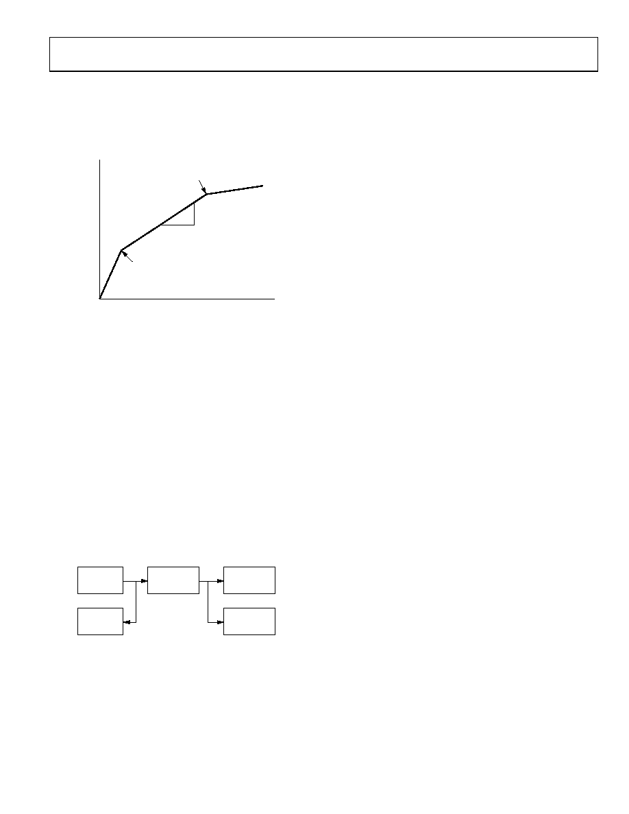
ROTATION POINT
COMPRESSION
REGION
GATE THRESHOLD
1
2
LIMITING REGION
0.1
1.0
10
15
500
40
O
UT
P
UT
(
mV
)
INPUT (mV)
Figure 30. Transfer Characteristic
EVALUATION BOARD SETUP PROCEDURE
When building a breadboard, keep the leads to Pin 3, Pin 4, and
Pin 5 short. An evaluation board is available from an Analog
Devices sales representative. The R and C designations refer to
the demonstration board schematic of Figure 26 and the parts
list in Table 7.
TEST EQUIPMENT SETUP
The recommended equipment and configuration are shown in
Figure 31. A low noise audio generator with a smooth output
adjustment range of 50 V to 50 mV is a suitable signal source.
A 40 dB pad is useful to reduce the level of most generators by
100× to simulate the microphone levels. The input voltmeter
can be connected before the pad and need only go down to
10 mV. The output voltmeter should go up to 2 V. The oscilloscope
is used to verify that the output is sinusoidal and that no clipping
occurs in the buffer, and to set the limiting and noise gating
knees.
00357-
030
AC
VOLTMETER
AC
VOLTMETER
SSM2166
EVALUATION
BOARD
SIGNAL
GENERATOR
OSCILLOSCOPE
Figure 31. Test Equipment Setup
Step 1: Configure the Buffer
The SSM2166 has an input buffer that can be used when the
overall gain required exceeds 20 dB, the maximum user-selectable
gain of the VCA. In the example, the desired output is 500 mV
for an input of ~15 mV, requiring a total gain of 30 dB. Set the
buffer gain at 20 dB and adjust the VCA for 10 dB. In the socket
pins provided on the evaluation board, insert R1 = 100 k and
R2 = 11 k. The buffer gain is set to 20 dB (×10).
Step 2: Initializing Potentiometers
With the power off, preset the potentiometers per Table 6.
Step 3: Testing Setup
With the power on, adjust the generator for an input level of
15 mV, 1 kHz. The output meter should indicate approximately
100 mV; if not, check the setup.
Step 4: Adjusting the Rotation Point
Set the input level to 15 mV and observe the output on the
oscilloscope. Adjust R3, ROTATION PT ADJ, until the output
level just begins to drop, then reverse so that the output is 500 mV.
The limiting has been set to 500 mV.
Step 5: Adjusting the VCA Gain
Set the input level to 15 mV. Adjust R10, GAIN ADJ, clockwise
(CW) for an output level of 500 mV. The VCA gain has been set
to 10 dB.
Step 6: Adjusting the Compression Ratio
Set the input signal for an output of 500 mV but not in limiting.
Note the value (around 15 mV). Next, reduce the input to 1/10
of the value noted (around 1.5 mV) for a change of 20 dB. Next,
adjust R6, COMP RATIO ADJ, CW until the output is 160 mV for
an output change of 10 dB. The compression, which is the
ratio of the output change to the input change, in decibels (dB),
has been set to 2:1.
Step 7: Setting the Noise Gate
With the input set at 100 V, observe the output on the oscilloscope
and adjust R7, NOISE GATE ADJ, CCW until the output drops
rapidly. Rock the control back and forth to find the knee. The
noise gate has been set to 100 V. The range of the noise gate is
from 0.3 mV to over 0.5 mV relative to the output of the buffer.
To fit this range to the application, it may be necessary to attenuate
the input or apportion the buffer gain and VCA gain differently.
Step 8: Listening
At this time, it may be desirable to connect an electret micro-
phone to the SSM2166 and listen to the results. Be sure to include
the proper power for the internal FET of the microphone
(usually 2 V dc to 5 V dc through a 2.2 k resistor). Experiment
with the settings to hear how the results change. Varying the
averaging capacitor, C4, changes the attack and decay times,
which are best determined empirically. The compression ratio
keeps the output steady over a range of microphone to speaker
distances, and the noise gate keeps the background sounds
subdued.
Step 9: Recording Values
With the power removed from the test fixture, measure and
record the values of all potentiometers, including any fixed
resistance in series with them. If the averaging capacitor, C4,
changes, also note its value.
相关PDF资料 |
PDF描述 |
|---|---|
| VE-26Z-IU-F4 | CONVERTER MOD DC/DC 2V 80W |
| VE-J5P-MY-B1 | CONVERTER MOD DC/DC 13.8V 50W |
| VI-B1M-IV-F2 | CONVERTER MOD DC/DC 10V 150W |
| MS27473E14B18SLC | CONN HSG PLUG 18POS STRGHT SCKT |
| VE-J5M-MY-B1 | CONVERTER MOD DC/DC 10V 50W |
相关代理商/技术参数 |
参数描述 |
|---|---|
| SSM2166SZ-REEL1 | 制造商:AD 制造商全称:Analog Devices 功能描述:Microphone Preamplifier with Variable Compression and Noise Gating |
| SSM2166SZ-REEL7 | 功能描述:IC PREAMP AUDIO MONO MIC 14SOIC RoHS:是 类别:集成电路 (IC) >> 线性 - 音頻放大器 系列:- 标准包装:80 系列:- 类型:AB 类 输出类型:1-通道(单声道) 在某负载时最大输出功率 x 通道数量:1.25W x 1 @ 8 欧姆 电源电压:2.5 V ~ 5.5 V 特点:消除爆音,差分输入,关闭,热保护 安装类型:表面贴装 供应商设备封装:8-MSOP-PowerPad 封装/外壳:8-TSSOP,8-MSOP(0.118",3.00mm 宽)裸露焊盘 包装:管件 配用:296-31419-ND - EVAL MODULE FOR TPA6205A1 其它名称:296-34563-5TPA6205A1DGN-ND |
| SSM2166SZ-REEL71 | 制造商:AD 制造商全称:Analog Devices 功能描述:Microphone Preamplifier with Variable Compression and Noise Gating |
| SSM2166SZ-X | 制造商:Analog Devices 功能描述:MICROPHONE PREAMPLIFIER W/VAR COMPRESS, ROHS - Rail/Tube |
| SSM2167 | 制造商:AD 制造商全称:Analog Devices 功能描述:Low Voltage Microphone Preamplifier with Variable Compression and Noise Gating |
发布紧急采购,3分钟左右您将得到回复。