- 您现在的位置:买卖IC网 > PDF目录69350 > ST62P00CB3/XXX (STMICROELECTRONICS) 8-BIT, MROM, 8 MHz, MICROCONTROLLER, PDIP16 PDF资料下载
参数资料
| 型号: | ST62P00CB3/XXX |
| 厂商: | STMICROELECTRONICS |
| 元件分类: | 微控制器/微处理器 |
| 英文描述: | 8-BIT, MROM, 8 MHz, MICROCONTROLLER, PDIP16 |
| 封装: | 0.300 INCH, PLASTIC, DIP-16 |
| 文件页数: | 23/100页 |
| 文件大小: | 1713K |
| 代理商: | ST62P00CB3/XXX |
第1页第2页第3页第4页第5页第6页第7页第8页第9页第10页第11页第12页第13页第14页第15页第16页第17页第18页第19页第20页第21页第22页当前第23页第24页第25页第26页第27页第28页第29页第30页第31页第32页第33页第34页第35页第36页第37页第38页第39页第40页第41页第42页第43页第44页第45页第46页第47页第48页第49页第50页第51页第52页第53页第54页第55页第56页第57页第58页第59页第60页第61页第62页第63页第64页第65页第66页第67页第68页第69页第70页第71页第72页第73页第74页第75页第76页第77页第78页第79页第80页第81页第82页第83页第84页第85页第86页第87页第88页第89页第90页第91页第92页第93页第94页第95页第96页第97页第98页第99页第100页
ST6200C ST6201C ST6203C
29/100
5.10 INTERRUPT HANDLING PROCEDURE
The interrupt procedure is very similar to a call pro-
cedure, in fact the user can consider the interrupt
as an asynchronous call procedure. As this is an
asynchronous event, the user cannot know the
context and the time at which it occurred. As a re-
sult, the user should save all Data space registers
which may be used within the interrupt routines.
The following list summarizes the interrupt proce-
dure:
When an interrupt request occurs, the following
actions are performed by the MCU automatically:
– The core switches from the normal flags to the
interrupt flags (or the NMI flags).
– The PC contents are stored in the top level of the
stack.
– The normal interrupt lines are inhibited (NMI still
active).
– The internal latch (if any) is cleared.
– The associated interrupt vector is loaded in the PC.
When an interrupt request occurs, the following
actions must be performed by the user software:
– User selected registers have to be saved within
the interrupt service routine (normally on a soft-
ware stack).
– The source of the interrupt must be determined
by polling the interrupt flags (if more than one
source is associated with the same vector).
– The RETI (RETurn from Interrupt) instruction
must end the interrupt service routine.
After the RETI instruction is executed, the MCU re-
turns to the main routine.
Caution: When a maskable interrupt occurs while
the ST6 core is in NORMAL mode and during the
execution of an “ldi IOR, 00h” instruction (disabling
all maskable interrupts): if the interrupt request oc-
curs during the first 3 cycles of the “ldi” instruction
(which is a 4-cycle instruction) the core will switch
to interrupt mode BUT the flags CN and ZN will
NOT switch to the interrupt pair CI and ZI.
5.10.1 Interrupt Response Time
This is defined as the time between the moment
when the Program Counter is loaded with the in-
terrupt vector and when the program has jump to
the interrupt subroutine and is ready to execute
the code. It depends on when the interrupt occurs
while the core is processing an instruction.
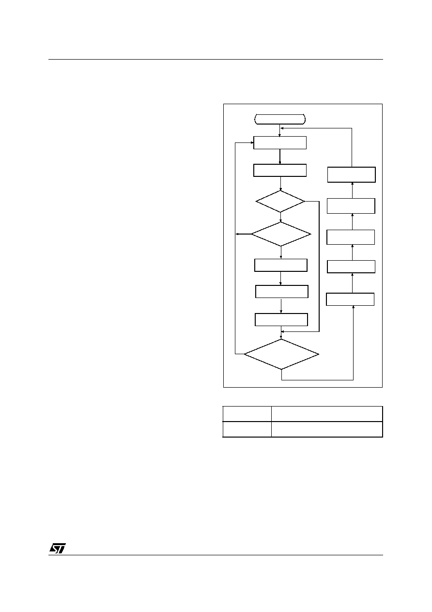
Figure 18. Interrupt Processing Flow Chart
Table 6. Interrupt Response Time
One CPU cycle is 13 external clock cycles thus 11
CPU cycles = 11 x (13 /8M) = 17.875 s with an 8
MHz external quartz.
Minimum
6 CPU cycles
Maximum
11 CPU cycles
INSTRUCTION
FETCH
INSTRUCTION
EXECUTE
INSTRUCTION
WAS
THE INSTRUCTION
A RETI?
ENABLE
MASKABLE INTERRUPTS
SELECT
NORMAL FLAGS
“POP”
THE STACKED PC
IS THERE AN
AN INTERRUPT REQUEST
AND INTERRUPT MASK?
SELECT
INTERRUPT FLAGS
PUSH THE
PC INTO THE STACK
LOAD PC FROM
INTERRUPT VECTOR
DISABLE
MASKABLE INTERRUPT
NO
YES
IS THE CORE
ALREADY IN
NORMAL MODE?
YES
NO
YES
CLEAR
INTERNAL LATCH *)
*) If a latch is present on the interrupt source line
1
相关PDF资料 |
PDF描述 |
|---|---|
| ST62T00CM6 | 8-BIT, OTPROM, 8 MHz, MICROCONTROLLER, PDSO16 |
| ST62T00CM1 | 8-BIT, OTPROM, 8 MHz, MICROCONTROLLER, PDSO16 |
| ST62T00CN1 | 8-BIT, OTPROM, 8 MHz, MICROCONTROLLER, PDSO16 |
| ST62T00CN6 | 8-BIT, OTPROM, 8 MHz, MICROCONTROLLER, PDSO16 |
| ST62T01CB3 | 8-BIT, OTPROM, 8 MHz, MICROCONTROLLER, PDIP16 |
相关代理商/技术参数 |
参数描述 |
|---|---|
| ST62P03CM1/MAM | 制造商:STMicroelectronics 功能描述: |
| ST62P08CM6/MHH/TR | 制造商:STMicroelectronics 功能描述: |
| ST62P08CM6/RCFTR | 制造商:STMicroelectronics 功能描述: |
| ST62P09CM1/REXTR | 制造商:STMicroelectronics 功能描述: |
| ST62P10CM6/FBS | 制造商:STMicroelectronics 功能描述: |
发布紧急采购,3分钟左右您将得到回复。