- 您现在的位置:买卖IC网 > PDF目录69350 > ST62P09CB6/XXX (STMICROELECTRONICS) 8-BIT, MROM, 8 MHz, MICROCONTROLLER, PDIP20 PDF资料下载
参数资料
| 型号: | ST62P09CB6/XXX |
| 厂商: | STMICROELECTRONICS |
| 元件分类: | 微控制器/微处理器 |
| 英文描述: | 8-BIT, MROM, 8 MHz, MICROCONTROLLER, PDIP20 |
| 封装: | 0.300 INCH, PLASTIC, DIP-20 |
| 文件页数: | 23/104页 |
| 文件大小: | 1487K |
| 代理商: | ST62P09CB6/XXX |
第1页第2页第3页第4页第5页第6页第7页第8页第9页第10页第11页第12页第13页第14页第15页第16页第17页第18页第19页第20页第21页第22页当前第23页第24页第25页第26页第27页第28页第29页第30页第31页第32页第33页第34页第35页第36页第37页第38页第39页第40页第41页第42页第43页第44页第45页第46页第47页第48页第49页第50页第51页第52页第53页第54页第55页第56页第57页第58页第59页第60页第61页第62页第63页第64页第65页第66页第67页第68页第69页第70页第71页第72页第73页第74页第75页第76页第77页第78页第79页第80页第81页第82页第83页第84页第85页第86页第87页第88页第89页第90页第91页第92页第93页第94页第95页第96页第97页第98页第99页第100页第101页第102页第103页第104页
ST6208C/ST6209C/ST6210C/ST6220C
25/104
RESET (Cont’d)
5.3.3 RESET Pin
The RESET pin may be connected to a device on
the application board in order to reset the MCU if
required. The RESET pin may be pulled low in
RUN, WAIT or STOP mode. This input can be
used to reset the internal state of the MCU and en-
sure it starts-up correctly. The pin, which is con-
nected to an internal pull-up, is active low and fea-
tures a Schmitt trigger input. A delay (2048 clock
cycles) added to the external signal ensures that
even short pulses on the RESET pin are accepted
as valid, provided VDD has completed its rising
phase and that the oscillator is running correctly
(normal RUN or WAIT modes). The MCU is kept in
the Reset state as long as the RESET pin is held
low.
If the RESET pin is grounded while the MCU is in
RUN or WAIT modes, processing of the user pro-
gram is stopped (RUN mode only), the I/O ports
are configured as inputs with pull-up resistors and
the main oscillator is restarted. When the level on
the RESET pin then goes high, the initialization se-
quence is executed at the end of the internal delay
period.
If the RESET pin is grounded while the MCU is in
STOP mode, the oscillator starts up and all the I/O
ports are configured as inputs with pull-up resis-
tors. When the RESET pin level then goes high,
the initialization sequence is executed at the end
of the internal delay period.
A simple external RESET circuitry is shown in Fig-
ure 15. For more details, please refer to the appli-
cation note AN669.
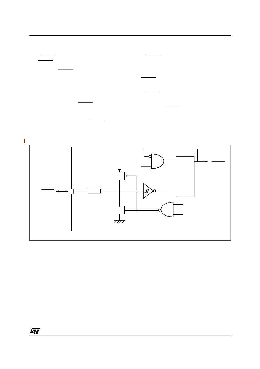
Figure 14. Reset Block Diagram
fINT
COU
N
TER
RESET
WATCHDOG RESET
LVD RESET
INTERNAL
RESET
RESD
1)
1) Resistive ESD protection.
VDD
RPU
2
048
clock
cycle
s
1
相关PDF资料 |
PDF描述 |
|---|---|
| ST62P09CM1/XXX | 8-BIT, MROM, 8 MHz, MICROCONTROLLER, PDSO20 |
| ST62T10CB3 | 8-BIT, OTPROM, 8 MHz, MICROCONTROLLER, PDIP20 |
| ST62T10CM1 | 8-BIT, OTPROM, 8 MHz, MICROCONTROLLER, PDSO20 |
| ST62P20CM1/XXX | 8-BIT, MROM, 8 MHz, MICROCONTROLLER, PDSO20 |
| ST62P20CN1/XXX | 8-BIT, MROM, 8 MHz, MICROCONTROLLER, PDSO20 |
相关代理商/技术参数 |
参数描述 |
|---|---|
| ST62P09CM1/REXTR | 制造商:STMicroelectronics 功能描述: |
| ST62P10CM6/FBS | 制造商:STMicroelectronics 功能描述: |
| ST62P15CM6/AITTR | 制造商:STMicroelectronics 功能描述: |
| ST62P52C | 制造商:STMicroelectronics 功能描述: |
| ST62P62CM6/MOMTR | 制造商:STMicroelectronics 功能描述: |
发布紧急采购,3分钟左右您将得到回复。