- 您现在的位置:买卖IC网 > PDF目录385870 > ST6397 (意法半导体) 8-BIT HCMOS MCUs FOR TV FREQUENCY SYNTHESIS WITH OSD PDF资料下载
参数资料
| 型号: | ST6397 |
| 厂商: | 意法半导体 |
| 英文描述: | 8-BIT HCMOS MCUs FOR TV FREQUENCY SYNTHESIS WITH OSD |
| 中文描述: | 8位微控制器HCMOS电视频率合成带OSD |
| 文件页数: | 12/68页 |
| 文件大小: | 560K |
| 代理商: | ST6397 |
第1页第2页第3页第4页第5页第6页第7页第8页第9页第10页第11页当前第12页第13页第14页第15页第16页第17页第18页第19页第20页第21页第22页第23页第24页第25页第26页第27页第28页第29页第30页第31页第32页第33页第34页第35页第36页第37页第38页第39页第40页第41页第42页第43页第44页第45页第46页第47页第48页第49页第50页第51页第52页第53页第54页第55页第56页第57页第58页第59页第60页第61页第62页第63页第64页第65页第66页第67页第68页
ST639x CORE
(Continued)
Indirect Registers (X,Y).
These two indirect reg-
istersare usedaspointerstothe memorylocations
in the dataspace. They are used in theregister-in-
direct addressing mode.These registers can be
addressed in the data space as RAM locations at
the 80h (X)and 81h (Y) addresses.They can also
be accessed with the direct, short direct, or bit di-
rect addressing modes. Accordingly, the ST639x
instructionsetcan use theindirectregistersas any
other registerof the data space.
Short Direct Registers (V, W).
These two regis-
ters are used to save one byte in short direct ad-
dressing mode.These registerscan be addressed
in the data space as RAM locations at the 82h (V)
and 83h (W) addresses. They can also be ac-
cessed with the direct and bit direct addressing
modes. Accordingly, the ST639x instruction set
can use the short direct registersas any other reg-
ister of the data space.
Program Counter (PC)
Theprogramcounterisa12-bitregisterthatcontains
the address of the next ROM location to be proc-
essed bythecore.ThisROMlocationmaybeanop-
code, an operand, or an address of operand. The
12-bit length allows the direct addressing of 4096
bytesin theprogramspace.Nevertheless,ifthepro-
gramspace containsmore than4096 locations,the
further program space can be addressed by using
the Program ROM Page Register. The PC value is
incremented, after it is read for the address of the
currentinstruction,bysendingitthroughtheALU,so
giving the address of the next byte in the program.
Toexecuterelative jumpsthe PC andtheoffsetval-
ues are shifted throughtheALU, wheretheywill be
added,andtheresultisshiftedbackintothePC.The
program counter can be changed in the following
ways:
JP (Jump) instruction....PC=Jump address
CALL instruction...........PC=Call address
Relative Branch
instructions...................PC=PC+offset
Interrupt........................PC=Interruptvector
Reset............................PC=Reset vector
RET & RETI instructions............PC=Pop (stack)
Normal instruction........PC=PC+1
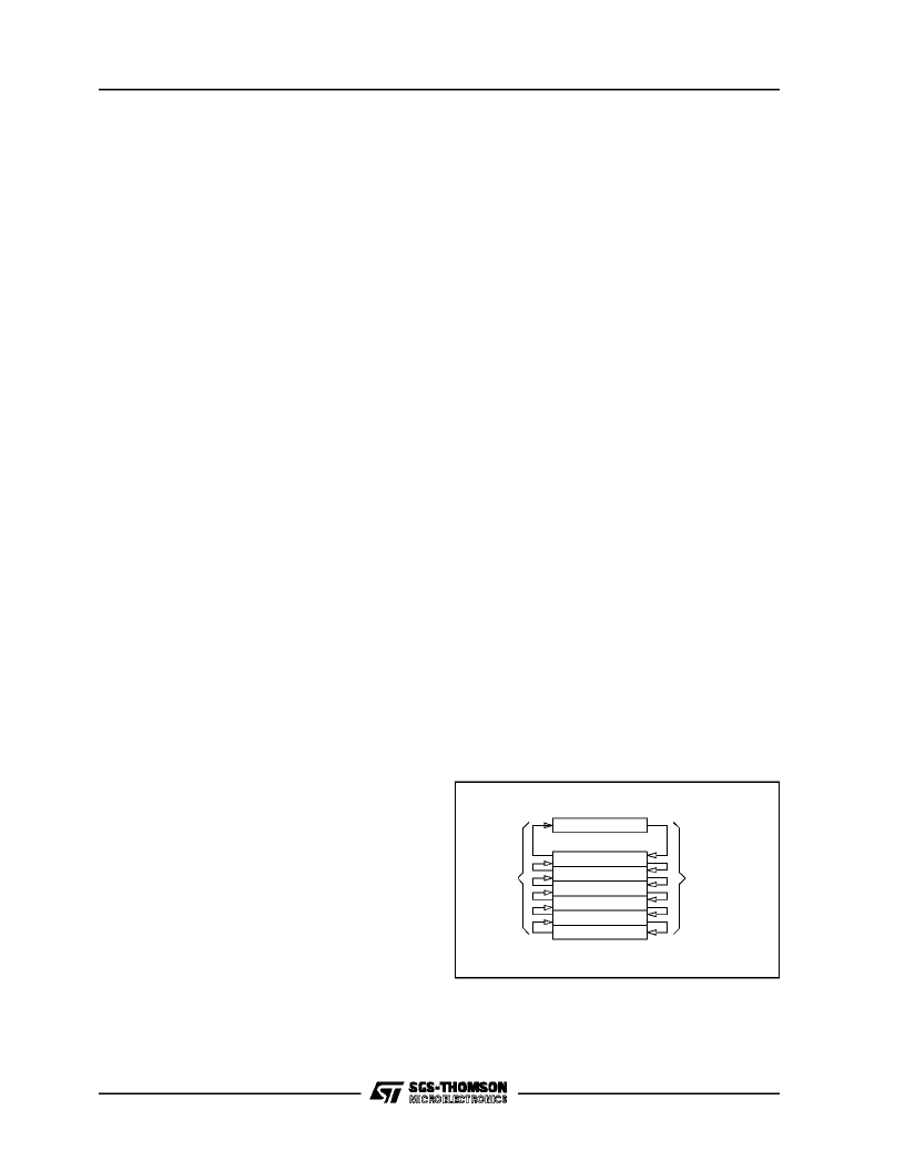
WHEN CALL
INTEROCCURS
STACK LEVEL 1
STACK LEVEL 2
STACK LEVEL 3
STACK LEVEL 4
STACK LEVEL 5
STACK LEVEL 6
PROGRAM COUNTER
WHEN
ROCCURS
VA000424
Figure 7. Stack Operation
Flags (C, Z)
The ST639x Core includes three pairs of flags that
correspond to 3 different modes: normal mode,in-
terrupt mode and Non-Maskable-Interrupt-Mode.
Each pair consists of a CARRY flag and a ZERO
flag. One pair (CN, ZN) is used duringnormal op-
eration, one pair is used during the interruptmode
(CI,ZI) andone isusedduring the not-maskablein-
terrupt mode (CNMI, ZNMI).
The ST639x Core uses the pair of flags that corre-
spondsto the actual mode: as soon as an interrupt
(resp. a Non-Maskable-Interrupt) is generated, the
ST639xCore uses the interrupt flags (resp. the NMI
flags)insteadof thenormalflags.WhentheRETI in-
structionis executed,thenormalflags(resp.theinter-
ruptflags) arerestoredif theMCU wasin the normal
mode(resp.intheinterruptmode)beforetheinterrupt.
Shouldbeobservedthateachflagsetcanonlybead-
dressed in its own routine (Not-maskable interrupt,
normal interrupt or main routine). The interrupt flags
are not cleared during the context switching and so,
theyremain inthestatetheywereattheexitofthelast
routineswitching.
The Carry flag is set when a carry or a borrow oc-
curs during arithmetic operations, otherwise it is
cleared. The Carry flag is also set to the value of
the bit tested in a bit test instruction, and partici-
pates in the rotate leftinstruction.
The Zeroflagis setif theresultofthelast arithmetic
or logical operation wasequal to zero, otherwise it
is cleared.
The switching between these three sets is auto-
matically performedwhen an NMI,an interrupt and
a RETI instructions occur. As the NMI mode is
automatically selected after the reset of the MCU,
the ST639xCore uses at first the NMI flags.
ST6391,92,93,95,97,99
8/64
相关PDF资料 |
PDF描述 |
|---|---|
| ST6399 | MOSFET; Transistor Polarity:P Channel; Drain Source Voltage, Vds:-30V; Continuous Drain Current, Id:-4.1A; On-Resistance, Rds(on):0.08ohm; Rds(on) Test Voltage, Vgs:-10V; Package/Case:8-1206; Leaded Process Compatible:No |
| ST63P06 | 8-BIT HCMOS PIGGYBACK MCUs FOR TV APPLICATIONS |
| ST63P07 | 8-BIT HCMOS PIGGYBACK MCUs FOR TV APPLICATIONS |
| ST63P08 | MOSFET; Drain Source Voltage, Vds:-20V; Continuous Drain Current, Id:-3.9A; On-Resistance, Rds(on):0.055ohm; Rds(on) Test Voltage, Vgs:-4.5V; Leaded Process Compatible:Yes; Mounting Type:Surface Mount; Package/Case:8-1206 RoHS Compliant: Yes |
| ST63P16 | MOSFET; Transistor Polarity:P Channel; Drain Source Voltage, Vds:-8V; Continuous Drain Current, Id:5.2A; On-Resistance, Rds(on):0.035ohm; Rds(on) Test Voltage, Vgs:-4.5V; Package/Case:8-1206; Leaded Process Compatible:No RoHS Compliant: No |
相关代理商/技术参数 |
参数描述 |
|---|---|
| ST6397B1 | 制造商:STMICROELECTRONICS 制造商全称:STMicroelectronics 功能描述:8-BIT HCMOS MCUs FOR TV FREQUENCY SYNTHESIS WITH OSD |
| ST6399 | 制造商:STMICROELECTRONICS 制造商全称:STMicroelectronics 功能描述:8-BIT HCMOS MCUs FOR TV FREQUENCY SYNTHESIS WITH OSD |
| ST6399B1 | 制造商:STMICROELECTRONICS 制造商全称:STMicroelectronics 功能描述:8-BIT HCMOS MCUs FOR TV FREQUENCY SYNTHESIS WITH OSD |
| ST63E126D1 | 制造商:STMICROELECTRONICS 制造商全称:STMicroelectronics 功能描述:8-BIT HCMOS MCUs FOR TV FREQUENCY & VOLTAGE SYNTHESIS WITH OSD |
| ST63E140D1 | 制造商:STMICROELECTRONICS 制造商全称:STMicroelectronics 功能描述:8-BIT HCMOS MCUs FOR TV FREQUENCY & VOLTAGE SYNTHESIS WITH OSD |
发布紧急采购,3分钟左右您将得到回复。