- 您现在的位置:买卖IC网 > PDF目录195890 > ST733C08LFM1L 1900 A, 800 V, SCR, TO-200AC PDF资料下载
参数资料
| 型号: | ST733C08LFM1L |
| 元件分类: | 晶闸管 |
| 英文描述: | 1900 A, 800 V, SCR, TO-200AC |
| 封装: | METAL CASE WITH CERAMIC INSULATOR, BPUK-3 |
| 文件页数: | 4/9页 |
| 文件大小: | 157K |
| 代理商: | ST733C08LFM1L |
ST733C..L Series
4
www.irf.com
Bulletin I25188 rev. A 04/00
T
J
Max. operating temperature range
-40 to 125
T
stg
Max. storage temperature range
-40 to 150
R
thJ-hs
Max. thermal resistance,
0.073
DC operation single side cooled
junction to heatsink
0.031
DC operation double side cooled
R
thC-hs Max. thermal resistance,
0.011
DC operation single side cooled
case to heatsink
0.005
DC operation double side cooled
F
Mounting force, ± 10%
14700
N
(1500)
(Kg)
wt
Approximate weight
255
g
Parameter
ST733C..L
Units
Conditions
K/W
Thermal and Mechanical Specification
°C
Case style
TO - 200AC (B-PUK)
See Outline Table
K/W
Single Side Double Side
180°
0.009
0.006
120°
0.011
90°
0.014
0.015
K/W
T
J = TJ max.
60°
0.020
0.021
0.022
30°
0.036
Sinusoidal conduction
Rectangular conduction
Conduction angle
Units
Conditions
R
thJ-hs
Conduction
(The following table shows the increment of thermal resistence R
thJ-hs when devices operate at different conduction angles than DC)
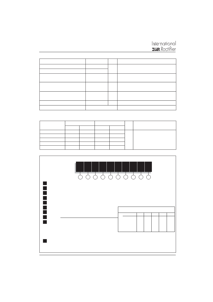
Ordering Information Table
5
68
9
ST
73
3
C
08
L
H
K
1
34
10
7
Device Code
12
1 - Thyristor
2 - Essential part number
3 - 3 = Fast turn off
4 - C = Ceramic Puk
5 - Voltage code: Code x 100 = V
RRM
(See Voltage Rating Table)
6 - L = Puk Case TO-200AC (B-PUK)
7 - Reapplied dv/dt code (for t
q
test condition)
8 -t
q
code
9 - 0 = Eyelet term. (Gate and Aux. Cathode Unsoldered Leads)
1 = Fast-on term. (Gate and Aux. Cathode Unsoldered Leads)
2 = Eyelet term. (Gate and Aux. Cathode Soldered Leads)
3 = Fast-on term. (Gate and Aux. Cathode Soldered Leads)
- Critical dv/dt:
None = 500V/sec (Standard value)
L
= 1000V/sec (Special selection)
dv/dt - t
q combinations available
dv/dt (V/s)
20
50
100
200
400
10
CN
DN
EN
--
12
CM
DM
EM
FM *
--
15
CL
DL
EL
FL *
HL
18
CP
DP
EP
FP
HP
20
CK
DK
EK
FK
H
t
q
(s)
* Standard part number.
All other types available only on request.
10
相关PDF资料 |
PDF描述 |
|---|---|
| ST733C08LFM3L | 1900 A, 800 V, SCR, TO-200AC |
| ST733C08LDP2PBF | 1900 A, 800 V, SCR, TO-200AC |
| ST733C08LDP2LPBF | 1900 A, 800 V, SCR, TO-200AC |
| ST733C08LDP3PBF | 1900 A, 800 V, SCR, TO-200AC |
| ST93003 | HIGH VOLTAGE FAST-SWITCHING PNP POWER TRANSISTOR |
相关代理商/技术参数 |
参数描述 |
|---|---|
| ST733C08LFM1PBF | 制造商:International Rectifier 功能描述:THYRISTOR 1900A 800V TO-200AC |
| ST7-34 | 制造商:SUPERWORLD 制造商全称:Superworld Electronics 功能描述:POWER TRANSFORMER |
| ST735 | 制造商:STMICROELECTRONICS 制造商全称:STMicroelectronics 功能描述:-5V INVERTING, NEGATIVE OUTPUT CURRENT-MODE PWM REGULATOR |
| ST735B2508L2 | 制造商:Marathon Special Products 功能描述: |
| ST735B2508R2 | 制造商:Marathon Special Products 功能描述: |
发布紧急采购,3分钟左右您将得到回复。