- 您现在的位置:买卖IC网 > PDF目录69373 > ST7FL19F1MATRE (STMICROELECTRONICS) 8-BIT, FLASH, 8 MHz, MICROCONTROLLER, PDSO20 PDF资料下载
参数资料
| 型号: | ST7FL19F1MATRE |
| 厂商: | STMICROELECTRONICS |
| 元件分类: | 微控制器/微处理器 |
| 英文描述: | 8-BIT, FLASH, 8 MHz, MICROCONTROLLER, PDSO20 |
| 封装: | 0.300 INCH, LEAD FREE, PLASTIC, SOP-20 |
| 文件页数: | 13/138页 |
| 文件大小: | 2515K |
| 代理商: | ST7FL19F1MATRE |
第1页第2页第3页第4页第5页第6页第7页第8页第9页第10页第11页第12页当前第13页第14页第15页第16页第17页第18页第19页第20页第21页第22页第23页第24页第25页第26页第27页第28页第29页第30页第31页第32页第33页第34页第35页第36页第37页第38页第39页第40页第41页第42页第43页第44页第45页第46页第47页第48页第49页第50页第51页第52页第53页第54页第55页第56页第57页第58页第59页第60页第61页第62页第63页第64页第65页第66页第67页第68页第69页第70页第71页第72页第73页第74页第75页第76页第77页第78页第79页第80页第81页第82页第83页第84页第85页第86页第87页第88页第89页第90页第91页第92页第93页第94页第95页第96页第97页第98页第99页第100页第101页第102页第103页第104页第105页第106页第107页第108页第109页第110页第111页第112页第113页第114页第115页第116页第117页第118页第119页第120页第121页第122页第123页第124页第125页第126页第127页第128页第129页第130页第131页第132页第133页第134页第135页第136页第137页第138页
ST7L15, ST7L19
11/138
FLASH PROGRAM MEMORY (cont’d)
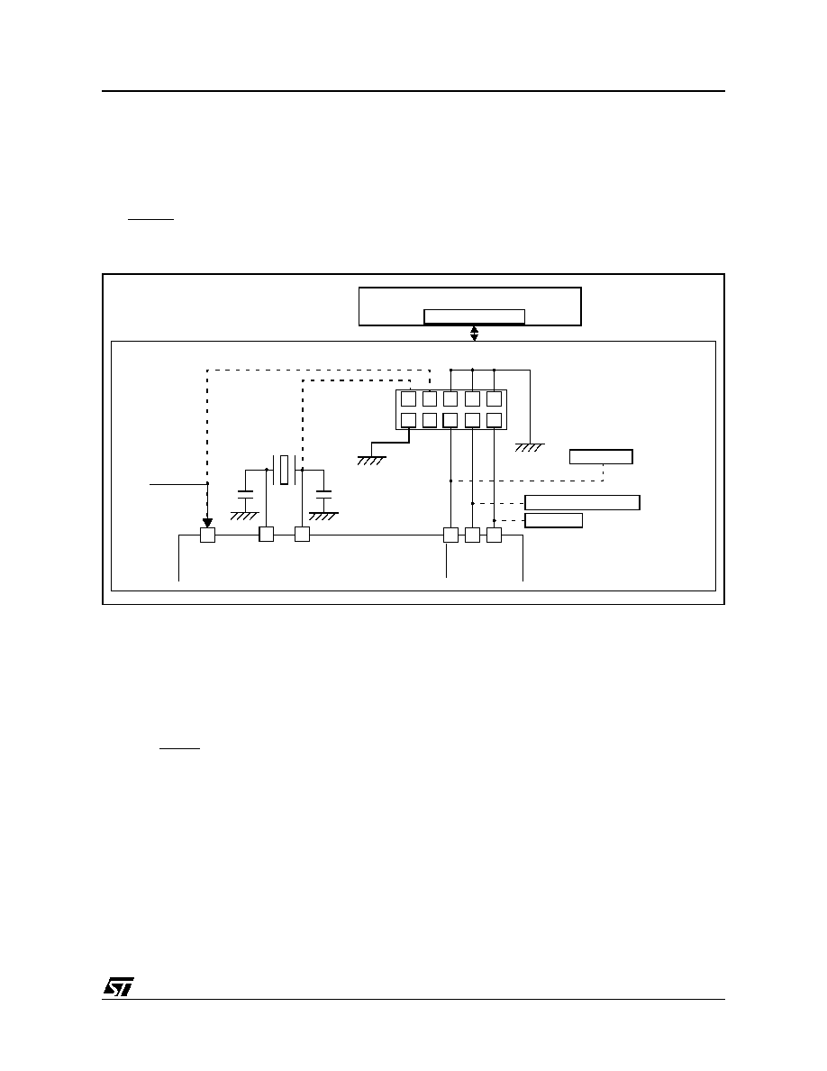
4.4 ICC INTERFACE
ICP needs a minimum of four and up to six pins to
be connected to the programming tool. These pins
are:
– RESET: Device reset
–VSS: Device power supply ground
– ICCCLK: ICC output serial clock pin
– ICCDATA: ICC input serial data pin
– OSC1: Main clock input for external source
(not required on devices without OSC1/OSC2
pins)
–VDD: Application board power supply (option-
al, see Note 3)
Figure 4. Typical ICC Interface
Notes:
1. If the ICCCLK or ICCDATA pins are only used as out-
puts in the application, no signal isolation is necessary. As
soon as the Programming Tool is plugged to the board,
even if an ICC session is not in progress, the ICCCLK and
ICCDATA pins are not available for the application. If they
are used as inputs by the application, isolation such as a
serial resistor must be implemented in case another de-
vice forces the signal. Refer to the Programming Tool
documentation for recommended resistor values.
2. During the ICP session, the programming tool must
control the RESET pin. This can lead to conflicts between
the programming tool and the application reset circuit if it
drives more than 5mA at high level (push-pull output or
pull-up resistor < 1K). A schottky diode can be used to
isolate the application RESET circuit in this case. When
using a classical RC network with R > 1K or a reset man-
agement
IC
with
open
drain
output
and
pull-up
resistor > 1K, no additional components are needed. In all
cases the user must ensure that no external reset is gen-
erated by the application during the ICC session.
3. The use of pin 7 of the ICC connector depends on the
Programming Tool architecture. This pin must be con-
nected when using most ST Programming Tools (it is
used to monitor the application power supply). Please re-
fer to the Programming Tool Manual.
4. Pin 9 must be connected to the OSC1 pin of the ST7
when the clock is not available in the application or if the
selected clock option is not programmed in the option
byte. On ST7 devices with multi-oscillator capability,
OSC2 must be grounded in this case.
5. In 38-pulse ICC mode, the internal RC oscillator is
forced as a clock source, regardless of the selection in the
option byte. For ST7L1 devices which do not support the
internal RC oscillator, the “option byte disabled” mode
must be used (35-pulse ICC mode entry, clock provided
by the tool).
Caution: During normal operation the ICCCLK pin
must be pulled up, internally or externally (external
pull-up of 10k mandatory in noisy environment).
This is to avoid entering ICC mode unexpectedly
during a reset. In the application, even if the pin is
configured as output, any reset puts it back in input
pull-up.
ICC CONNECTOR
ICCDAT
A
ICCCL
K
RESE
T
VDD
HE10 CONNECTOR TYPE
APPLICATION
POWER SUPPLY
1
2
4
6
8
10
97
5
3
PROGRAMMING TOOL
ICC CONNECTOR
APPLICATION BOARD
ICC Cable
(See Note 3)
ST7
CL2
CL1
OSC1
OSC2
OPTIONAL
See Note 1
See Note 1 and Caution
See Note 2
APPLICATION
RESET SOURCE
APPLICATION
I/O
(See Note 4)
1
相关PDF资料 |
PDF描述 |
|---|---|
| ST7FL34F2MCE | 8-BIT, FLASH, 8 MHz, MICROCONTROLLER, PDSO20 |
| ST7FL38F2MAE | 8-BIT, FLASH, 8 MHz, MICROCONTROLLER, PDSO20 |
| ST7FL35F2UCRE | 8-BIT, FLASH, 8 MHz, MICROCONTROLLER, QCC20 |
| ST7FL38F2MAXE | 8-BIT, FLASH, 8 MHz, MICROCONTROLLER, PDSO20 |
| ST7FL38F2UAE | 8-BIT, FLASH, 8 MHz, MICROCONTROLLER, QCC20 |
相关代理商/技术参数 |
参数描述 |
|---|---|
| ST7FL19F1MCE | 制造商:STMicroelectronics 功能描述: |
| ST7FL19F1MCRE | 制造商:STMICROELECTRONICS 制造商全称:STMicroelectronics 功能描述:8-bit MCU for automotive with single voltage Flash/ROM memory, data EEPROM, ADC, 5 timers, SPI |
| ST7FL19F1MCTRE | 制造商:STMICROELECTRONICS 制造商全称:STMicroelectronics 功能描述:8-bit MCU for automotive with single voltage Flash/ROM memory, data EEPROM, ADC, 5 timers, SPI |
| ST7FL34F2MAE | 功能描述:8位微控制器 -MCU 8-bit MCU Automotive RoHS:否 制造商:Silicon Labs 核心:8051 处理器系列:C8051F39x 数据总线宽度:8 bit 最大时钟频率:50 MHz 程序存储器大小:16 KB 数据 RAM 大小:1 KB 片上 ADC:Yes 工作电源电压:1.8 V to 3.6 V 工作温度范围:- 40 C to + 105 C 封装 / 箱体:QFN-20 安装风格:SMD/SMT |
| ST7FL34F2MCE | 制造商:STMicroelectronics 功能描述:8-BIT MCU FOR AUTOMOTIVE WITH SINGLE VOLTAGE FLASH/ROM - Rail/Tube |
发布紧急采购,3分钟左右您将得到回复。