- 您现在的位置:买卖IC网 > PDF目录69373 > ST7FL19F1MATRE (STMICROELECTRONICS) 8-BIT, FLASH, 8 MHz, MICROCONTROLLER, PDSO20 PDF资料下载
参数资料
| 型号: | ST7FL19F1MATRE |
| 厂商: | STMICROELECTRONICS |
| 元件分类: | 微控制器/微处理器 |
| 英文描述: | 8-BIT, FLASH, 8 MHz, MICROCONTROLLER, PDSO20 |
| 封装: | 0.300 INCH, LEAD FREE, PLASTIC, SOP-20 |
| 文件页数: | 15/138页 |
| 文件大小: | 2515K |
| 代理商: | ST7FL19F1MATRE |
第1页第2页第3页第4页第5页第6页第7页第8页第9页第10页第11页第12页第13页第14页当前第15页第16页第17页第18页第19页第20页第21页第22页第23页第24页第25页第26页第27页第28页第29页第30页第31页第32页第33页第34页第35页第36页第37页第38页第39页第40页第41页第42页第43页第44页第45页第46页第47页第48页第49页第50页第51页第52页第53页第54页第55页第56页第57页第58页第59页第60页第61页第62页第63页第64页第65页第66页第67页第68页第69页第70页第71页第72页第73页第74页第75页第76页第77页第78页第79页第80页第81页第82页第83页第84页第85页第86页第87页第88页第89页第90页第91页第92页第93页第94页第95页第96页第97页第98页第99页第100页第101页第102页第103页第104页第105页第106页第107页第108页第109页第110页第111页第112页第113页第114页第115页第116页第117页第118页第119页第120页第121页第122页第123页第124页第125页第126页第127页第128页第129页第130页第131页第132页第133页第134页第135页第136页第137页第138页
ST7L15, ST7L19
111/138
ELECTRICAL CHARACTERISTICS (cont’d)
13.7 EMC CHARACTERISTICS
Susceptibility tests are performed on a sample ba-
sis during product characterization.
13.7.1
Functional
EMS
(Electro
Magnetic
Susceptibility)
Based on a simple running application on the
product (toggling two LEDs through I/O ports), the
product is stressed by two electro magnetic events
until a failure occurs (indicated by the LEDs).
■ ESD: Electro-Static Discharge (positive and
negative) is applied on all pins of the device until
a functional disturbance occurs. This test
conforms with the IEC 1000-4-2 standard.
■ FTB: A Burst of Fast Transient voltage (positive
and negative) is applied to VDD and VSS through
a 100pF capacitor, until a functional disturbance
occurs. This test conforms with the IEC 1000-4-
4 standard.
A device reset allows normal operations to
resume. The test results are given in the table be-
low based on the EMS levels and classes defined
in application note AN1709.
13.7.1.1 Designing Hardened Software to Avoid
Noise Problems
EMC characterization and optimization are per-
formed at component level with a typical applica-
tion environment and simplified MCU software. It
should be noted that good EMC performance is
highly dependent on the user application and the
software in particular.
Therefore, it is recommended that EMC software
optimization and prequalification tests are made
relative to the EMC level requested for the user's
application.
Software recommendations:
The software flowchart must include the manage-
ment of runaway conditions such as:
– Corrupted program counter
– Unexpected reset
– Critical data corruption (control registers...)
Prequalification trials:
Most of the common failures (unexpected reset
and program counter corruption) can be repro-
duced by manually forcing a low state on the RE-
SET pin or the Oscillator pins for 1 second.
To complete these trials, ESD stress can be ap-
plied directly on the device, over the range of
specification values. When unexpected behavior
is detected, the software can be hardened to pre-
vent unrecoverable errors occurring (see applica-
tion note AN1015).
13.7.2 Electro Magnetic Interference (EMI)
Based on a simple application running on the
product (toggling two LEDs through the I/O ports),
the product is monitored in terms of emission. This
emission test is in line with the norm SAE J 1752/
3 which specifies the board and the loading of
each pin.
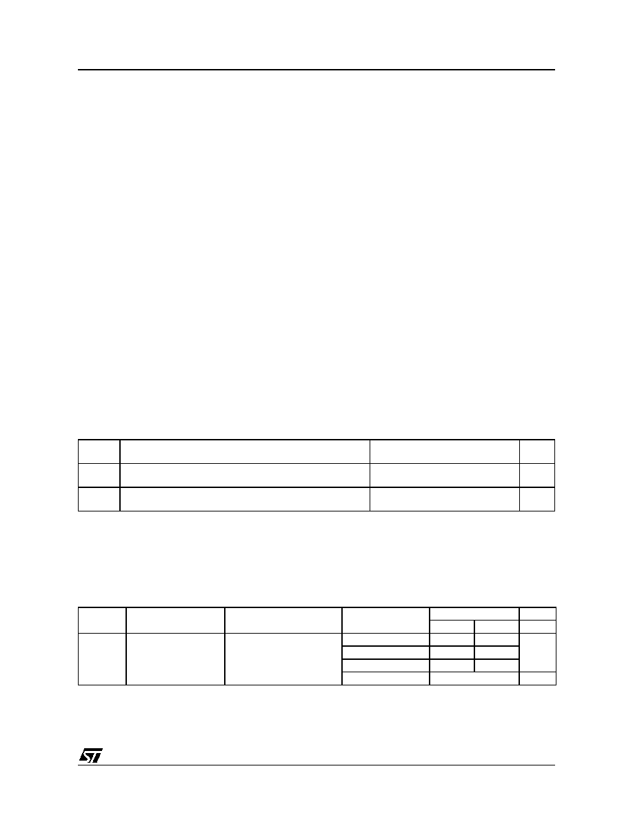
Notes:
1. Data based on characterization results, not tested in production.
Symbol
Parameter
Conditions
Level/
Class
VFESD
Voltage limits to be applied on any I/O pin to induce a function-
al disturbance
VDD = 5V, TA = 25°C, fOSC = 8MHz,
conforms to IEC 1000-4-2
2B
VFFTB
Fast transient voltage burst limits to be applied through 100pF
on VDD and VDD pins to induce a functional disturbance
VDD = 5V, TA = 25°C, fOSC = 8MHz,
conforms to IEC 1000-4-4
3B
Symbol
Parameter
Conditions
Monitored
Frequency Band
Max vs [fOSC/fCPU]Unit
8/4 MHz
16/8 MHz
SEMI
Peak level1)
VDD = 5V, TA = 25°C,
SO20 package,
conforming to SAE J 1752/3
0.1 MHz to 30 MHz
15
20
dBV
30 MHz to 130 MHz
17
21
130 MHz to 1 GHz
12
15
SAE EMI Level
3
-
相关PDF资料 |
PDF描述 |
|---|---|
| ST7FL34F2MCE | 8-BIT, FLASH, 8 MHz, MICROCONTROLLER, PDSO20 |
| ST7FL38F2MAE | 8-BIT, FLASH, 8 MHz, MICROCONTROLLER, PDSO20 |
| ST7FL35F2UCRE | 8-BIT, FLASH, 8 MHz, MICROCONTROLLER, QCC20 |
| ST7FL38F2MAXE | 8-BIT, FLASH, 8 MHz, MICROCONTROLLER, PDSO20 |
| ST7FL38F2UAE | 8-BIT, FLASH, 8 MHz, MICROCONTROLLER, QCC20 |
相关代理商/技术参数 |
参数描述 |
|---|---|
| ST7FL19F1MCE | 制造商:STMicroelectronics 功能描述: |
| ST7FL19F1MCRE | 制造商:STMICROELECTRONICS 制造商全称:STMicroelectronics 功能描述:8-bit MCU for automotive with single voltage Flash/ROM memory, data EEPROM, ADC, 5 timers, SPI |
| ST7FL19F1MCTRE | 制造商:STMICROELECTRONICS 制造商全称:STMicroelectronics 功能描述:8-bit MCU for automotive with single voltage Flash/ROM memory, data EEPROM, ADC, 5 timers, SPI |
| ST7FL34F2MAE | 功能描述:8位微控制器 -MCU 8-bit MCU Automotive RoHS:否 制造商:Silicon Labs 核心:8051 处理器系列:C8051F39x 数据总线宽度:8 bit 最大时钟频率:50 MHz 程序存储器大小:16 KB 数据 RAM 大小:1 KB 片上 ADC:Yes 工作电源电压:1.8 V to 3.6 V 工作温度范围:- 40 C to + 105 C 封装 / 箱体:QFN-20 安装风格:SMD/SMT |
| ST7FL34F2MCE | 制造商:STMicroelectronics 功能描述:8-BIT MCU FOR AUTOMOTIVE WITH SINGLE VOLTAGE FLASH/ROM - Rail/Tube |
发布紧急采购,3分钟左右您将得到回复。