- 您现在的位置:买卖IC网 > PDF目录69381 > STEL-1175+125/MC (INTEL CORP) 8-BIT, DSP-NUM CONTROLLED OSCILLATOR, CQCC68 PDF资料下载
参数资料
| 型号: | STEL-1175+125/MC |
| 厂商: | INTEL CORP |
| 元件分类: | 数字信号处理外设 |
| 英文描述: | 8-BIT, DSP-NUM CONTROLLED OSCILLATOR, CQCC68 |
| 封装: | CERAMIC, LDCC-68 |
| 文件页数: | 8/14页 |
| 文件大小: | 253K |
| 代理商: | STEL-1175+125/MC |
3
STEL-1175+125
PIN CONNECTIONS
1
PHASE1
2
PHASE2
3
PHASE3
4
PHASE4
5
PHASE5
6
DATA0
7
DATA1
8
DATA2
9
DATA3
10 DATA4
11 DATA5
12 DATA6
13 DATA7
14 PHASE6
15 PHASE7
16 PHASE8
17 PHASE9
18 PHASE10
19 PHASE11
20 WRSTB
21 PHSEL
22 I.C.
23 RESET
24 ROUND
25 SINE
26 FRSEL
27 VDD
28 VSS
29 FRLD
30 COUT
31 CSEL
32 PHLD
33 PHCLK
34 VSS
35 VDD
36 OUT0(LSB)
37 OUT1
38 OUT2
39 OUT3
40 OUT4
41 N.C.
42 VSS
43 VDD
44 OUT5
45 OUT6
46 OUT7
47 OUT8
48 OUT9
49 OUT10
50 OUT11
51 VSS
52 VDD
53 N.C.
54 N.C.
55 N.C.
56 FSYNC
57 PSYNC
58 ADDR0
59 VSS
60 VDD
61 ADDR1
62 ADDR2
63 ADDR3
64 CLOCK
65 CIN
66 VDD
67 VSS
68 PHASE0
Notes: 1. I.C. denotes Internal Connection. These pins must be left unconnected. Do not use for vias.
2. Connect all unused inputs to Vss, leave unused outputs unconnected.
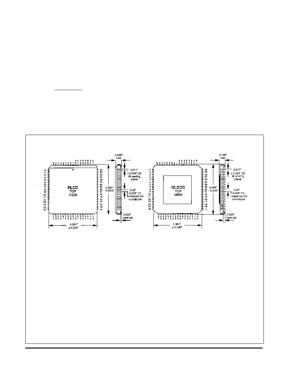
Package: 68 pin PLCC
Thermal coefficient, θja = 35°/W
Package: 68 pin CLDCC
Thermal coefficient, θja = 34°C/W
PIN CONFIGURATION
The NCO maintains a record of phase which is accurate to
32 bits. At each clock cycle, the number stored in the 32-
bit -Phase register is added to the previous value of the
phase accumulator. The number in the phase accumulator
represents the current phase of the synthesized sine and
cosine functions. The number in the -Phase register
represents the phase change for each cycle of the clock.
This number is directly related to the output frequency by
the following:
fc x -Phase
fo=
232
where: fo is the frequency of the output signal
and: fc is the clock frequency.
The sine and cosine functions are generated from the 13
most significant bits of the phase accumulator. The
frequency of the NCO is determined by the number stored
in the -Phase Register, which may be programmed by an
8-bit microprocessor.
The NCO generates a sampled sine wave where the
sampling function is the clock. The practical upper limit of
the NCO output frequency is about 40% of the clock
frequency due to spurious components that are created by
sampling. Those components are at frequencies greater
than half the clock frequency and can be removed by
filtering.
The phase noise of the NCO output signal may be
determined from the phase noise of the clock signal input
and the ratio of the output frequency to the clock
相关PDF资料 |
PDF描述 |
|---|---|
| STEL-1177/CF | 8-BIT, DSP-NUM CONTROLLED OSCILLATOR, CPGA84 |
| STG2000XC | SPECIALTY MICROPROCESSOR CIRCUIT, PQFP208 |
| STK17C88-W45 | REAL TIME CLOCK, PDIP40 |
| STK17T88-R25I | REAL TIME CLOCK, PDSO48 |
| STK17T88-R45 | REAL TIME CLOCK, PDSO48 |
相关代理商/技术参数 |
参数描述 |
|---|---|
| STEL-1176/CM | 制造商:未知厂家 制造商全称:未知厂家 功能描述:Numeric-Controlled Oscillator |
| STEL-1176/MC | 制造商:未知厂家 制造商全称:未知厂家 功能描述:Numeric-Controlled Oscillator |
| STEL-1177/CC | 制造商:未知厂家 制造商全称:未知厂家 功能描述:Numeric-Controlled Oscillator |
| STEL-1177/CF | 制造商:未知厂家 制造商全称:未知厂家 功能描述:Numeric-Controlled Oscillator |
| STEL-1177/CM | 制造商:未知厂家 制造商全称:未知厂家 功能描述:Numeric-Controlled Oscillator |
发布紧急采购,3分钟左右您将得到回复。