- 您现在的位置:买卖IC网 > PDF目录98148 > STK17TA8RF25I REAL TIME CLOCK, PDSO48 PDF资料下载
参数资料
| 型号: | STK17TA8RF25I |
| 元件分类: | 时钟/数据恢复及定时提取 |
| 英文描述: | REAL TIME CLOCK, PDSO48 |
| 封装: | 0.300 INCH, 0.025 INCH PITCH, ROHS COMPLIANT, PLASTIC, SSOP-48 |
| 文件页数: | 10/27页 |
| 文件大小: | 712K |
| 代理商: | STK17TA8RF25I |
第1页第2页第3页第4页第5页第6页第7页第8页第9页当前第10页第11页第12页第13页第14页第15页第16页第17页第18页第19页第20页第21页第22页第23页第24页第25页第26页第27页
STK17TA8
July 2006
Document Control #ML0025 rev 1.4
18
Setting all match bits to 0 will
require an exact time/date match. Note: The product
requires match bit for seconds alarm register
(1x1FFF2 – D7) be set to 0 for proper operation of
the Alarm Flag and Interrupt.
The alarm value should be initialized on power-up by
software since the alarm registers are not non-
volatile.
WATCHDOG TIMER
The watchdog timer is intended to interrupt to
processor should its program get hung in a loop and
not respond in a timely manner. The software must
reload the watchdog timer before it counts down to
zero to prevent this interrupt.
The watchdog timer is a free running down counter
that uses the 32 Hz clock (31.25 ms) derived from the
crystal oscillator. The watchdog timer function does
no operate unless the oscillator is running.
The watchdog counter is loaded with a starting value
from the load register and then counts down to zero
setting the watchdog flag (WDF) and generating an
interrupt if the watchdog interrupt is enabled. The
watchdog flag bit is reset when the flag register is
read. The operating software would normally reload
the counter by setting and then resetting the
watchdog strobe bit (WDS) within the timing interval
programmed in the load register.
The procedure to set a new value into the load
register begins when the watchdog write bit (/WDW)
is set to zero and then a new value is written into the
watchdog register at 01x1FFF7). Once the new value
is loaded, the watchdog write bit is set to 1 and the
watchdog strobe bit (WDS) is set to 1 to load this
value into the load register. The watchdog strobe bit
is then set to zero. Note: Setting the load register to
zero will disable the watchdog timer function.
The system software should initialize the watchdog
load register on power-up to the desired value since
the register is not non-volatile.
POWER MONITOR
The STK17TA8 provides a power management
scheme with power-fail interrupt capability. It also
controls the internal switch to backup power for the
clock and protects the memory from low-VCC access.
The power monitor is based on an internal band-gap
reference circuit that compares the VCC voltage to
various thresholds.
As described in the AutoStore section previously,
when Vswitch is reached as VCC decays from power
loss, a data store operation is initiated from SRAM to
the nonvolatile elements, securing the last SRAM
data state. Power is also switched from VCC to the
backup supply (battery or capacitor) to operate the
RTC oscillator.
When operating from the backup source no data may
be read or written and the clock functions are not
available to the user. The clock continues to operate
in the background. Updated clock data is available to
the user after tHRECALL delay (See AutoStore
/POWER-UP RECALL) after VCC has been restored
to the device.
INTERRUPTS
The STK17TA8 provides three potential interrupt
sources. They include the watchdog timer, the power
monitor, and the clock/calendar alarm. Each can be
individually enabled and assigned to drive the INT pin.
In addition, each has an associated flag bit that the
host processor can use to determine the cause of the
interrupt.
Some of the sources have additional control bits that
determine functional behavior. In addition, the pin
driver has three bits that specify its behavior when an
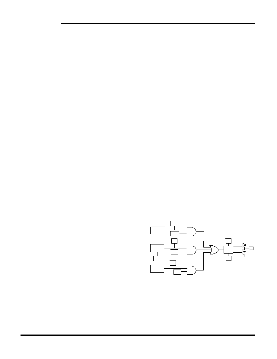
interrupt occurs. A functional diagram of the interrupt
logic is shown below.
The three interrupts each have a source and an
enable. Both the source and the enable must be
active (true high) in order to generate an interrupt
output. Only one source is necessary to drive the pin.
The user can identify the source by reading the
Flags/Control register, which contains the flags
associated with each source. All flags are cleared to 0
Figure 7. Interrupt Block Diagram
Watchdog
Timer
Power
Monitor
Clock
Alarm
PF
PFE
VINT
AIE
AF
P/L
H/L
Pin
Driver
INT
VCC
WIE
WDF
VSS
相关PDF资料 |
PDF描述 |
|---|---|
| STLED316SMTR | 4 X 17 SEGMENTS SEGMENT LED DRVR AND DSPL CTLR, PDSO24 |
| STM32F101C8T6 | 32-BIT, FLASH, 36 MHz, RISC MICROCONTROLLER, PQFP48 |
| STM32F101R6T6 | 32-BIT, FLASH, 36 MHz, RISC MICROCONTROLLER, PQFP64 |
| STM32F101VBT6 | 32-BIT, FLASH, 36 MHz, RISC MICROCONTROLLER, PQFP100 |
| STM32F101T6U6 | 32-BIT, FLASH, 36 MHz, RISC MICROCONTROLLER, QCC36 |
相关代理商/技术参数 |
参数描述 |
|---|---|
| STK17TA8-RF25I | 功能描述:NVRAM 128Kbx8+RTC 2.7-3.6V RoHS:否 制造商:Maxim Integrated 数据总线宽度:8 bit 存储容量:1024 Kbit 组织:128 K x 8 接口类型:Parallel 访问时间:70 ns 电源电压-最大:5.5 V 电源电压-最小:4.5 V 工作电流:85 mA 最大工作温度:+ 70 C 最小工作温度:0 C 封装 / 箱体:EDIP 封装:Tube |
| STK17TA8-RF25IL | 制造商:Cypress Semiconductor 功能描述: |
| STK17TA8-RF25ITR | 功能描述:NVRAM 128Kbx8+RTC 2.7-3.6V RoHS:否 制造商:Maxim Integrated 数据总线宽度:8 bit 存储容量:1024 Kbit 组织:128 K x 8 接口类型:Parallel 访问时间:70 ns 电源电压-最大:5.5 V 电源电压-最小:4.5 V 工作电流:85 mA 最大工作温度:+ 70 C 最小工作温度:0 C 封装 / 箱体:EDIP 封装:Tube |
| STK17TA8-RF25TR | 功能描述:NVRAM 128Kbx8+RTC 2.7-3.6V RoHS:否 制造商:Maxim Integrated 数据总线宽度:8 bit 存储容量:1024 Kbit 组织:128 K x 8 接口类型:Parallel 访问时间:70 ns 电源电压-最大:5.5 V 电源电压-最小:4.5 V 工作电流:85 mA 最大工作温度:+ 70 C 最小工作温度:0 C 封装 / 箱体:EDIP 封装:Tube |
| STK17TA8-RF35 | 制造商:SIM 功能描述: |
发布紧急采购,3分钟左右您将得到回复。