参数资料
| 型号: | SY10E136JZTR |
| 厂商: | Micrel Inc |
| 文件页数: | 7/9页 |
| 文件大小: | 0K |
| 描述: | IC COUNTER U/D 6BIT UNIV 28-PLCC |
| 标准包装: | 750 |
| 系列: | 10E |
| 逻辑类型: | 二进制计数器 |
| 方向: | 上,下 |
| 元件数: | 1 |
| 每个元件的位元数: | 6 |
| 复位: | 异步 |
| 计时: | 同步 |
| 计数速率: | 650MHz |
| 触发器类型: | 正边沿 |
| 电源电压: | 4.2 V ~ 5.5 V |
| 工作温度: | 0°C ~ 85°C |
| 安装类型: | 表面贴装 |
| 封装/外壳: | 28-LCC(J 形引线) |
| 供应商设备封装: | 28-PLCC |
| 包装: | 带卷 (TR) |
| 其它名称: | SY10E136JZ TR |
7
SY10E136
SY100E136
Micrel, Inc.
M9999-032006
hbwhelp@micrel.com or (408) 955-1690
count status for the next occurrence of terminal count on
the LSC. This ripple propagation will not affect the count
frequency as it has 26-1 or 63 clock pulses to ripple through
without affecting the count operation of the chain.
The only limiting factor which could reduce the count
frequency of the chain as compared to a free running single
device will be the set-up time of the CLIN input. This limit
will consist of the CLK to CLOUT delay of the E136, plus the
CLIN set-up time, plus any path length differences between
the CLOUT output and the clock.
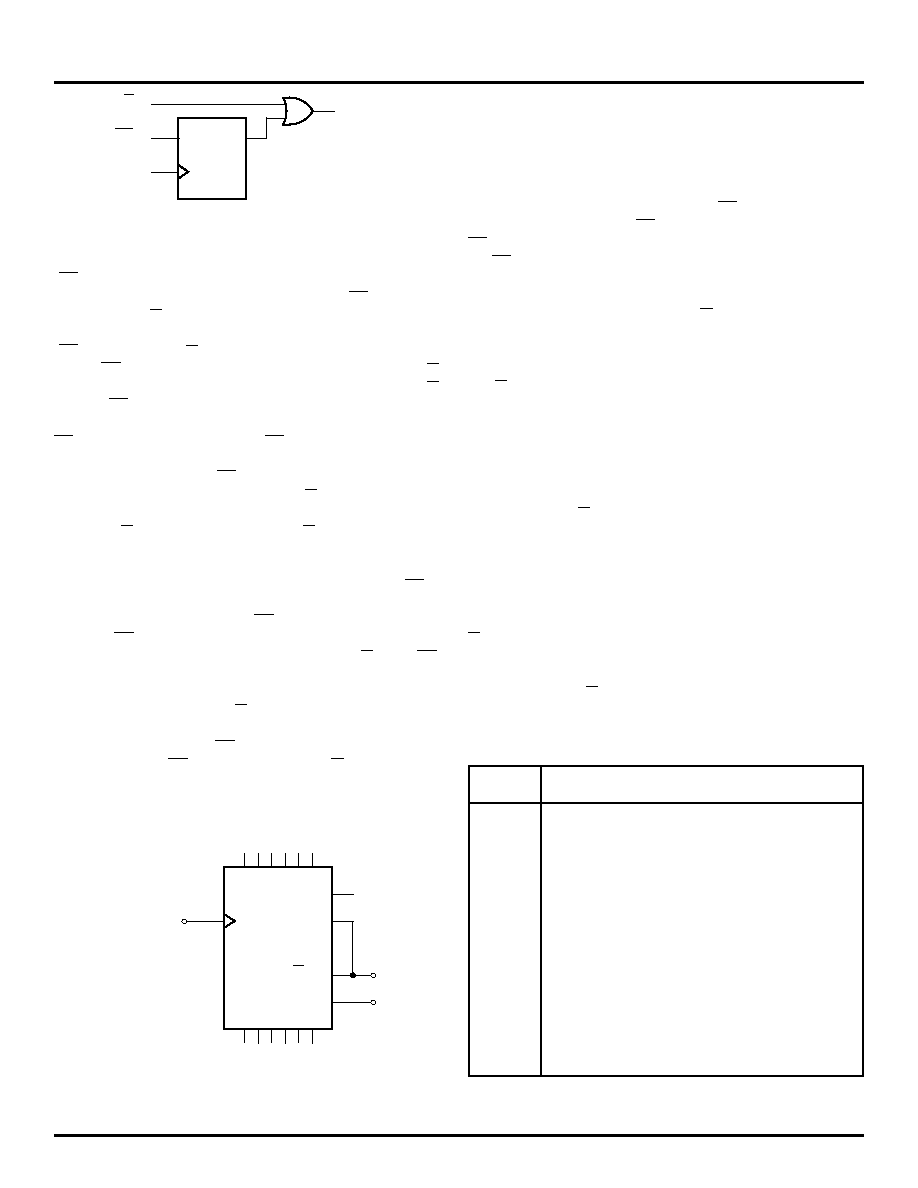
Programmable Divider
Using external feedback of the COUT pin, the E136 can
be configured as a programmable divider. Figure 3 illustrates
the configuration for a 6-bit count-down programmable
divider. If for some reason a count-up divider is preferred,
the COUT signal is simply fed back to S2 rather than S1.
Examination of the truth table for the E136 shows that when
both S1 and S2 are LOW, the counter will parallel load on
the next positive transition of the clock. If the S2 input is
low and the S1 input is high, the counter will be in the
count-down mode and will count towards an all zero state
upon successive clock pulses.
Knowing this and the
operation of the COUT output, it becomes a trivial matter to
build programmable dividers.
For a programmable divider, one must to load a
predesignated number into the counter and count to terminal
count. Upon terminal count, the counter should automatically
reload the divide number. With the architecture shown in
Figure 3, when the counter reaches terminal count, the
COUT output, and thus the S1 input, will go LOW.
This,
combined with the low on S2 will cause the counter to load
the inputs present on D0–D5. Upon loading the divide value
into the counter, COUT will go HIGH as the counter is no
longer at terminal count, thereby placing the counter back
into the count mode.
CLK
CIN
CLIN
ACTIVE
LOW
DQ
Figure 2. Look-Ahead-Carry Input Structure
Note from the waveforms that the look-ahead-carry output
(CLOUT) pulses low one clock pulse before the counter
reaches terminal count. Also note that both CLOUT and the
carry-out pin (COUT) of the device pulse low for only one
clock period.
The input structure for look-ahead-carry-in
(CLIN) and carry-in (CIN) is pictured in Figure 2.
The CLIN input is registered and then OR'ed with the CIN
input. From the truth table one can see that both the CIN
and the CLIN inputs must be in a LOW state for the E136 to
be enabled to count (either count up or count down). The
CLIN inputs are driven by the CLOUT output of the lower
order E136 and, therefore, are only asserted for a single
clock period. Since the CLIN input is registered, it must be
asserted one clock period prior to the CIN input.
If the counter previous to a given counter is at terminal
count, its COUT output, and thus the CIN input of the given
counter will be in the "LOW" state. This signals the given
counter that it will need to count one upon the next terminal
count of the least significant counter (LSC).
The CLOUT
output of the LSC will pulse low one clock period before it
reaches terminal count. This CLOUT signal will be clocked
into the CLIN input of the higher order counters on the
following positive clock transition. Since both CIN and CLIN
are in the LOW state, the next clock pulse will cause the
least significant counter to roll over and all higher order
counters, if signaled by the CIN inputs, to count by one.
During the clock pulse in which the higher order counter
is counting by one, the CLIN is clocking in the high signal
presented by the CLOUT of the LSC. The CINs in the higher
order counter will ripple through the chain to update the
CLK
CLOCK
COUT
Q0 – Q5
D0 – D5
S0
S1
"LO"
COUT
Figure 3. 6-bit Programmable Divider
Divide
Preset Data Inputs
Ratio
D5
D4
D3
D2
D1
D0
2L
L
H
3L
L
H
L
4L
L
H
5L
L
H
L
**
*
**
*
36
H
L
H
37
H
L
H
L
38
H
L
H
L
H
**
*
**
*
62
HH
L
H
63
HH
H
L
64
HH
H
Table 1. Preset Inputs Versus Divide Ratio
相关PDF资料 |
PDF描述 |
|---|---|
| SY10E137JC | IC COUNTER RIPPLE 8-BIT 28-PLCC |
| SY10E143JZ | IC HOLD REGISTER 9BIT 28-PLCC |
| SY10E150JZ TR | IC LATCH 6BIT D-TYPE 28PLCC |
| SY10E175JC | IC LATCH 9-BIT W/PARITY 28-PLCC |
| SY10E431JZ TR | IC FLIP FLOP 3BIT DIFF 28-PLCC |
相关代理商/技术参数 |
参数描述 |
|---|---|
| SY10E137JC | 功能描述:IC COUNTER RIPPLE 8-BIT 28-PLCC RoHS:否 类别:集成电路 (IC) >> 逻辑 -计数器,除法器 系列:10E 产品变化通告:1Q2012 Discontinuation 30/Mar/2012 标准包装:2,500 系列:74HC 逻辑类型:二进制计数器 方向:上 元件数:1 每个元件的位元数:12 复位:异步 计时:- 计数速率:50MHz 触发器类型:负边沿 电源电压:2 V ~ 6 V 工作温度:-55°C ~ 125°C 安装类型:表面贴装 封装/外壳:16-TSSOP(0.173",4.40mm 宽) 供应商设备封装:16-TSSOP 包装:带卷 (TR) |
| SY10E137JZ | 功能描述:计数器移位寄存器 8-bit Ripple Counter (Lead Free) RoHS:否 制造商:Texas Instruments 计数器类型: 计数顺序:Serial to Serial/Parallel 电路数量:1 封装 / 箱体:SOIC-20 Wide 逻辑系列: 逻辑类型: 输入线路数量:1 输出类型:Open Drain 传播延迟时间:650 ns 最大工作温度:+ 125 C 最小工作温度:- 40 C 封装:Reel |
| SY10E137JZ TR | 功能描述:计数器移位寄存器 8-bit Ripple Counter (Lead Free) RoHS:否 制造商:Texas Instruments 计数器类型: 计数顺序:Serial to Serial/Parallel 电路数量:1 封装 / 箱体:SOIC-20 Wide 逻辑系列: 逻辑类型: 输入线路数量:1 输出类型:Open Drain 传播延迟时间:650 ns 最大工作温度:+ 125 C 最小工作温度:- 40 C 封装:Reel |
| SY10E141JC | 功能描述:IC SHIFT REGISTER 8-BIT 28-PLCC RoHS:否 类别:集成电路 (IC) >> 逻辑 - 移位寄存器 系列:10E 标准包装:1,000 系列:- 逻辑类型:移位寄存器 输出类型:差分 元件数:1 每个元件的位元数:4 功能:串行至并行 电源电压:4.2 V ~ 5.7 V 工作温度:-40°C ~ 85°C 安装类型:表面贴装 封装/外壳:24-SOIC(0.295",7.50mm 宽) 供应商设备封装:24-SOIC 包装:带卷 (TR) |
| SY10E141JC TR | 功能描述:IC SHIFT REGISTER 8-BIT 28-PLCC RoHS:否 类别:集成电路 (IC) >> 逻辑 - 移位寄存器 系列:10E 标准包装:1,000 系列:- 逻辑类型:移位寄存器 输出类型:差分 元件数:1 每个元件的位元数:4 功能:串行至并行 电源电压:4.2 V ~ 5.7 V 工作温度:-40°C ~ 85°C 安装类型:表面贴装 封装/外壳:24-SOIC(0.295",7.50mm 宽) 供应商设备封装:24-SOIC 包装:带卷 (TR) |
发布紧急采购,3分钟左右您将得到回复。