- 您现在的位置:买卖IC网 > PDF目录98185 > TC9446FG SPECIALTY CONSUMER CIRCUIT, PQFP100 PDF资料下载
参数资料
| 型号: | TC9446FG |
| 元件分类: | 消费家电 |
| 英文描述: | SPECIALTY CONSUMER CIRCUIT, PQFP100 |
| 封装: | 14 X 20 MM, 0.65 MM PITCH, PLASTIC, QFP-100 |
| 文件页数: | 39/41页 |
| 文件大小: | 562K |
| 代理商: | TC9446FG |
第1页第2页第3页第4页第5页第6页第7页第8页第9页第10页第11页第12页第13页第14页第15页第16页第17页第18页第19页第20页第21页第22页第23页第24页第25页第26页第27页第28页第29页第30页第31页第32页第33页第34页第35页第36页第37页第38页当前第39页第40页第41页
TC9446FG
2005-09-28
7
Description of Operation
1.
Micro Controller Interface
The TC9446FG can perform transmission and reception of serial data with a micro controller in the
serial mode or the I2C mode.
MIMD terminal performs a change in the serial mode and the I2C mode, and input and output of data
are performed at MSB first.
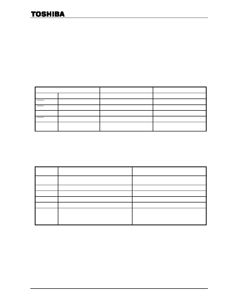
The use terminal and the function in the serial mode and the I2C mode are shown in Table 1.
The bit composition of a 24 bit command is shown in Table 2.
Note 4: This data sheet shows the general control method, refer to the program explanation data of an
attached sheet for a detailed command list, the control method, etc.
Table 1
Use Terminal and Function in the Serial Mode and the I
2
C Mode
Transmission Mode
Serial Mode (MIMD
= L)
I
2
C Mode (MIMD
= H)
Terminal
Input/Output
Functions
MICS
Input (3-5 V)
Chip selection signal input
Not used (fixed “L”)
MILP
Input (3-5 V)
Latch pulse signal input
Not used (fixed “L”)
MIDIO
Input (3-5 V)/Output (3 V)
Data input/output
Data input/output (SDA)
MICK
Input (3-5 V)
Clock input
Clock input (SCL)
MIACK
Output (3 V)
Acknowledge signal output and out of
control detection output
Out of control detection output
Note 5: MIDIO terminal needs pull-up resistance for the terminal exterior because of an open-drain output.
When using it by I
2
C bus, pull-up resistance is required also for MICK terminal.
Note 6: The addresses of an I
2
C bus are write-in address 3Ah and read-out address 3Bh.
Table 2
Bit Composition of 24 Bit Command
Bit Assign
Functions
Remarks
23-8
16 bit address
Refer to the command list of the program explanation
data sheet
7
Starting the incorrect operation detection output
Starting the incorrect operation detection output by “1”
6
Starting the program RAM boot
Starting the program RAM boot by “1”
5
Setting the soft reset
Setting the soft reset ON by “1”
4
Setting the Read/Write (R/W)
Setting the read by “1”
3-0
Setting the number of words for transmission
“0h”; a word
↓
“Fh”; 16 words
相关PDF资料 |
PDF描述 |
|---|---|
| TC9447F | SPECIALTY CONSUMER CIRCUIT, PQFP100 |
| TC9452F | SPECIALTY CONSUMER CIRCUIT, PQFP44 |
| TC9456F | SPECIALTY CONSUMER CIRCUIT, PQFP44 |
| TC9459F | 2 CHANNEL(S), VOLUME CONTROL CIRCUIT, PDSO24 |
| TC9459N | 2 CHANNEL(S), VOLUME CONTROL CIRCUIT, PDIP28 |
相关代理商/技术参数 |
参数描述 |
|---|---|
| TC9447F | 制造商:TOSHIBA 制造商全称:Toshiba Semiconductor 功能描述:Single-Chip Audio Digital Signal Processor |
| TC9452F | 制造商:TOSHIBA 制造商全称:Toshiba Semiconductor 功能描述:SINGLE CHIP SURROUND LSI |
| TC9455F | 制造商:TOSHIBA 制造商全称:Toshiba Semiconductor 功能描述:TOSHIBA CMOS Digital Integrated Circuit Silicon Monolithic |
| TC9455N | 制造商:TOSHIBA 制造商全称:Toshiba Semiconductor 功能描述:TOSHIBA CMOS Digital Integrated Circuit Silicon Monolithic |
| TC9456F | 制造商:TOSHIBA 制造商全称:Toshiba Semiconductor 功能描述:SINGLE CHIP SURROUND LSI WITH A BUILT-IN SRS |
发布紧急采购,3分钟左右您将得到回复。