- 您现在的位置:买卖IC网 > PDF目录98204 > TDA9115 (STMICROELECTRONICS) HORIZ/VERT DEFLECTION IC, PDIP32 PDF资料下载
参数资料
| 型号: | TDA9115 |
| 厂商: | STMICROELECTRONICS |
| 元件分类: | 偏转 |
| 英文描述: | HORIZ/VERT DEFLECTION IC, PDIP32 |
| 封装: | SHRINK, PLASTIC, DIP-32 |
| 文件页数: | 20/45页 |
| 文件大小: | 675K |
| 代理商: | TDA9115 |
第1页第2页第3页第4页第5页第6页第7页第8页第9页第10页第11页第12页第13页第14页第15页第16页第17页第18页第19页当前第20页第21页第22页第23页第24页第25页第26页第27页第28页第29页第30页第31页第32页第33页第34页第35页第36页第37页第38页第39页第40页第41页第42页第43页第44页第45页
TDA9115
27/45
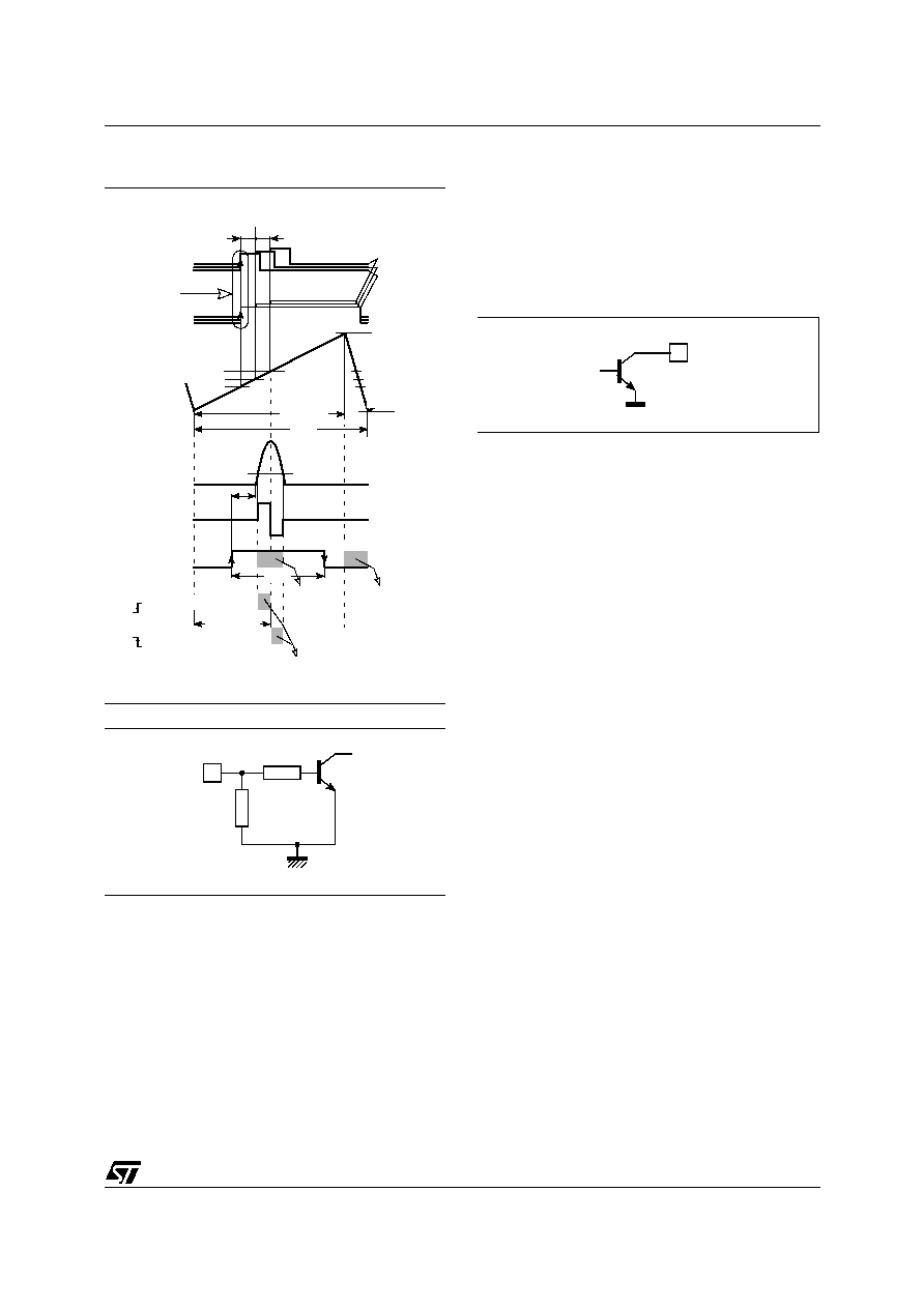
Figure 7. Horizontal timing diagram
Figure 8. HFly input configuration
9.3.6 Output section
The H-drive signal is inhibited (high level) during
flyback pulse, and also when VCC is too low, when
I2C bus bit HBOutEn is set to 0 (default position).
The PLL2 is followed by a rapid phase shifting
which accepts the signal from H-moiré canceller
(see sub chapter Horizontal moiré cancellation on
page 27)
The output stage consists of a NPN bipolar tran-
sistor, the collector of which is routed to HOut pin
(see Figure 9).
Figure 9. HOut configuration
Non-conductive state of HOT (Horizontal Output
Transistor) must correspond to non-conductive
state of the device output transistor.
9.3.7 Soft-start and soft-stop on H-drive
The soft-start and soft-stop procedure is carried
out at each switch-on or switch-off of the H-drive
signal via HBOutEn I2C bus bit to protect external
power components. By its second function, the ex-
ternal capacitor on pin HPosF is used to time out
this procedure, during which the duty cycle of H-
drive signal starts at its maximum (“tHoff/TH for soft
start/stop” in electrical specifications) and slowly
decreases. This is controlled by voltage on pin
HPosF. See Figure 10 and sub chapter Safety
functions on page 33.
9.3.8 Horizontal moiré cancellation
The horizontal moiré canceller is intended to blur a
potential beat between the horizontal video pixel
period and the CRT pixel width, which causes vis-
ible moiré patterns in the picture.
On pin HMoiré, it generates a square line-synchro-
nized waveform with amplitude adjustable through
HMOIRE I2C bus control.
The behaviour of horizontal moiré is to be opti-
mised for different deflection design configurations
using HMoiré I2C bus bit. This bit is to be kept at 0
for common architecture (B+ and EHT common
regulation) and at 1 for separated architecture (B+
and EHT each regulated separately).
00000
H-flyback
PLL2
H-drive
current
VThrHFly
control
+
-
(on HOut)
tS
tHoff
H-drive
region
H-drive
region
tph(max)
inhibited
tS: HOT storage time
H-Osc
VS(0)
7/8TH
TH
VHOThrHi
max.
med.
min.
VHPosF
H-sync
(polarized)
REF1
tHph
min
max
HPOS
(I2C)
max.
med.
min.
PLL1 lock
(internal)
VHOThrLo
(VCO)
P
LL2
PLL1
control
ON
forced high
00000000000000000000000000000000000000000000
000000000000000000000000000000000000000000
forced low
OFF
ON
0
GND
~20k
HFly 12
~500
int.
ext.
00
26
int.
ext.
HOut
相关PDF资料 |
PDF描述 |
|---|---|
| TDA9116 | HORIZ/VERT DEFLECTION IC, PDIP32 |
| TDA9141N | COLOR SIGNAL DECODER, PDIP32 |
| TDA9170N | SPECIALTY CONSUMER CIRCUIT, PDIP32 |
| TDA9177N | SPECIALTY CONSUMER CIRCUIT, PDIP24 |
| TDA9201 | 1 CHANNEL, VIDEO PREAMPLIFIER, PDIP20 |
相关代理商/技术参数 |
参数描述 |
|---|---|
| TDA9116 | 制造商:STMICROELECTRONICS 制造商全称:STMicroelectronics 功能描述:LOW-COST I2C CONTROLLED DEFLECTION PROCESSOR FOR MULTISYNC MONITOR |
| TDA9118 | 制造商:PHILIPS 制造商全称:NXP Semiconductors 功能描述:行/场扫描处理电路 |
| TDA9141 | 制造商:PHILIPS 制造商全称:NXP Semiconductors 功能描述:PAL/NTSC/SECAM decoder/sync processor |
| TDA9143 | 制造商:PHILIPS 制造商全称:NXP Semiconductors 功能描述:I2C-bus controlled, alignment-free PAL/NTSC/SECAM decoder/sync processor |
| TDA9144 | 制造商:PHILIPS 制造商全称:NXP Semiconductors 功能描述:I2C-bus controlled, alignment-free PAL/NTSC/SECAM decoder/sync processor with PALplus helper demodulator |
发布紧急采购,3分钟左右您将得到回复。