- 您现在的位置:买卖IC网 > PDF目录98252 > TLV320ADC3001IYZHR (TEXAS INSTRUMENTS INC) 2-CH 16-BIT PROPRIETARY METHOD ADC, SERIAL ACCESS, PBGA16 PDF资料下载
参数资料
| 型号: | TLV320ADC3001IYZHR |
| 厂商: | TEXAS INSTRUMENTS INC |
| 元件分类: | ADC |
| 英文描述: | 2-CH 16-BIT PROPRIETARY METHOD ADC, SERIAL ACCESS, PBGA16 |
| 封装: | GREEN, DSBGA-16 |
| 文件页数: | 7/81页 |
| 文件大小: | 836K |
| 代理商: | TLV320ADC3001IYZHR |
第1页第2页第3页第4页第5页第6页当前第7页第8页第9页第10页第11页第12页第13页第14页第15页第16页第17页第18页第19页第20页第21页第22页第23页第24页第25页第26页第27页第28页第29页第30页第31页第32页第33页第34页第35页第36页第37页第38页第39页第40页第41页第42页第43页第44页第45页第46页第47页第48页第49页第50页第51页第52页第53页第54页第55页第56页第57页第58页第59页第60页第61页第62页第63页第64页第65页第66页第67页第68页第69页第70页第71页第72页第73页第74页第75页第76页第77页第78页第79页第80页第81页
DA(6)
DA(0)
RA(7)
RA(0)
D(7)
D(0)
Start
(M)
7-bit Device Address
(M)
Write
(M)
Slave
Ack
(S)
8-bit Register Address
(M)
Slave
Ack
(S)
8-bit Register Data
(M)
Stop
(M)
Slave
Ack
(S)
SDA
SCL
(M) => SDA Controlled by Master
(S) => SDA Controlled by Slave
DA(6)
DA(0)
RA(7)
RA(0)
Start
(M)
7-bit Device Address
(M)
Write
(M)
Slave
Ack
(S)
8-bit Register Address
(M)
Slave
Ack
(S)
SDA
SCL
DA(6)
DA(0)
7-bit Device Address
(M)
Read
(M)
Slave
Ack
(S)
D(7)
D(0)
8-bit Register Data
(S)
Stop
(M)
Master
No Ack
(M)
Repeat
Start
(M)
(M) => SDA Controlled by Master
(S) => SDA Controlled by Slave
SLAS548C
– OCTOBER 2008 – REVISED APRIL 2011
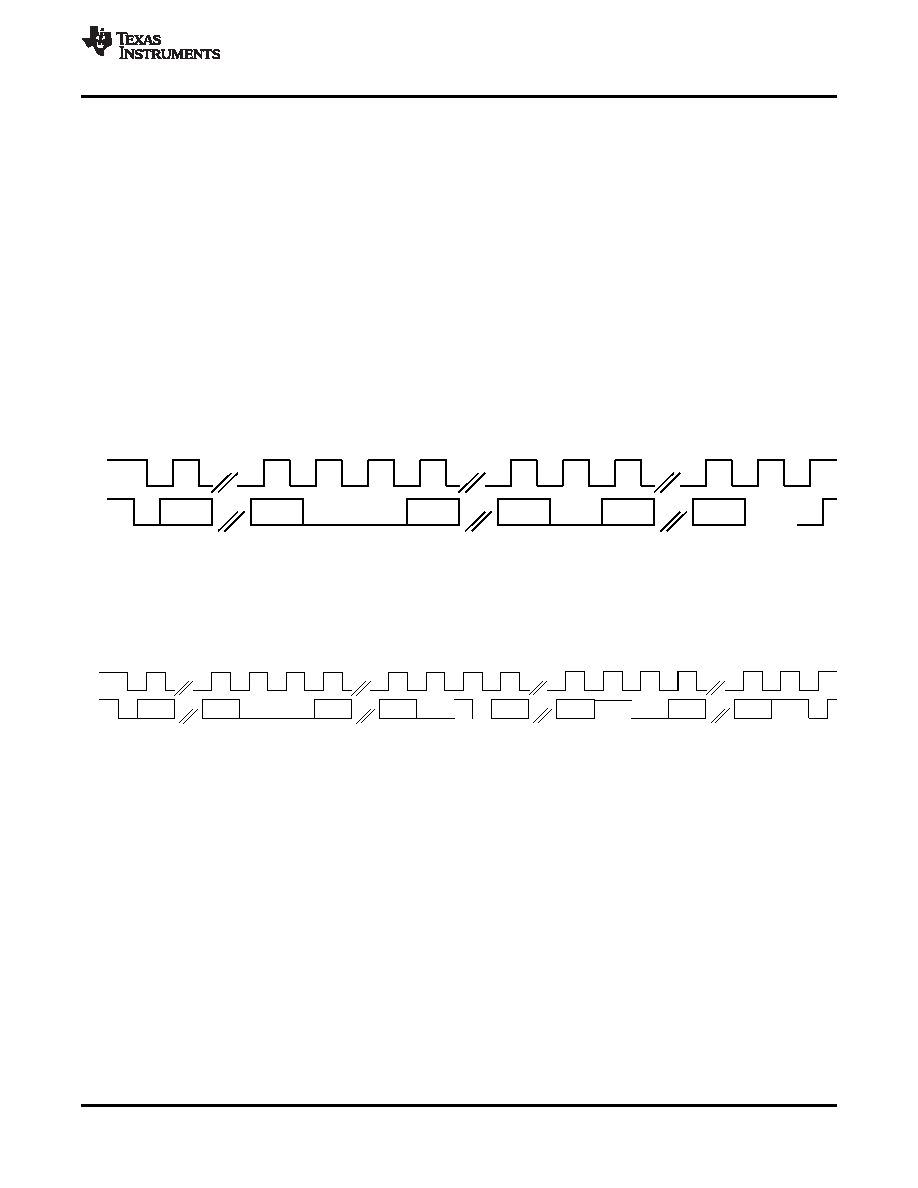
After the master issues a START condition, it sends a byte that indicates the slave device with which it is to
communicate. This byte is called the address byte. Each device on an I2C bus has a unique 7-bit address to
which it responds. (Slaves can also have 10-bit addresses; see the I2C specification for details.) The master
sends an address in the address byte, together with a bit that indicates whether it is to read from or write to the
slave device.
Every byte transmitted on the I2C bus, whether it is address or data, is acknowledged with an acknowledge bit.
When a master has finished sending a byte (eight data bits) to a slave, it stops driving SDA and waits for the
slave to acknowledge the byte. The slave acknowledges the byte by pulling SDA LOW. The master then sends a
clock pulse to clock the acknowledge bit. Similarly, when a master has finished reading a byte, it pulls SDA LOW
to acknowledge this to the slave. It then sends a clock pulse to clock the bit.
A not-acknowledge is performed by leaving SDA HIGH during an acknowledge cycle. If a device is not present
on the bus, and the master attempts to address it, it receives a not-acknowledge because no device is present at
that address to pull the line LOW.
When a master has finished communicating with a slave, it may issue a STOP condition. When a STOP
condition is issued, the bus becomes idle again. A master may also issue another START condition. When a
START condition is issued while the bus is active, it is called a repeated START condition.
The TLV320ADC3001 also responds to and acknowledges a general call, which consists of the master issuing a
command with a slave address byte of 00h.
Figure 12. I2C Write
Figure 13. I2C Read
In the case of an I2C register write, if the master does not issue a STOP condition, then the device enters
auto-increment mode. So in the next eight clocks, the data on SDA is treated as data for the next incremental
register.
Similarly, in the case of an I2C register read, after the device has sent out the 8-bit data from the addressed
register, if the master issues an ACKNOWLEDGE, the slave takes over control of SDA bus and transmits for the
next eight clocks the data of the next incremental register.
DIGITAL AUDIO DATA SERIAL INTERFACE
Audio data is transferred between the host processor and the TLV320ADC3001 via the digital-audio serial-data
interface, or audio bus. The audio bus on this device is flexible, including left- or right-justified data options,
support for I2S or PCM protocols, programmable data-length options, a TDM mode for multichannel operation,
flexible master/slave configurability for each bus clock line, and the ability to communicate with multiple devices
within a system directly.
Copyright
2008–2011, Texas Instruments Incorporated
15
相关PDF资料 |
PDF描述 |
|---|---|
| TLV320ADC3101IRGER320 | SPECIALTY CONSUMER CIRCUIT, PQCC24 |
| TLV320ADC3101IRGET320 | SPECIALTY CONSUMER CIRCUIT, PQCC24 |
| TLV320ADC3101IRGER | SPECIALTY CONSUMER CIRCUIT, PQCC24 |
| TLV320ADC3101IRGET | SPECIALTY CONSUMER CIRCUIT, PQCC24 |
| TLV320AIC10C | SPECIALTY CONSUMER CIRCUIT, PQFP48 |
相关代理商/技术参数 |
参数描述 |
|---|---|
| TLV320ADC3001IYZHT | 功能描述:音频模/数转换器 IC 92dB 16b Low-Pwr Stereo ADC RoHS:否 制造商:Wolfson Microelectronics 转换速率: 分辨率: ADC 输入端数量: 工作电源电压: 最大工作温度: 最小工作温度: 安装风格: 封装 / 箱体: 封装: |
| TLV320ADC3001IYZHT | 制造商:Texas Instruments 功能描述:Analog/Digital (A/D) Converter IC |
| TLV320ADC3101 | 制造商:TI 制造商全称:Texas Instruments 功能描述:Low Power Stereo ADC for Wireless Handsets and Portable Audio |
| TLV320ADC3101EVM-K | 功能描述:音频 IC 开发工具 TLV320ADC3101EVM-K Eval Mod RoHS:否 制造商:Texas Instruments 产品:Evaluation Kits 类型:Audio Amplifiers 工具用于评估:TAS5614L 工作电源电压:12 V to 38 V |
| TLV320ADC3101IRGER | 功能描述:音频模/数转换器 IC 92dB (16B) Low Power Stereo ADC RoHS:否 制造商:Wolfson Microelectronics 转换速率: 分辨率: ADC 输入端数量: 工作电源电压: 最大工作温度: 最小工作温度: 安装风格: 封装 / 箱体: 封装: |
发布紧急采购,3分钟左右您将得到回复。