- 您现在的位置:买卖IC网 > PDF目录19512 > TMS320DM648ZUT9 (Texas Instruments)IC DGTL MEDIA PROC 529-FCBGA PDF资料下载
参数资料
| 型号: | TMS320DM648ZUT9 |
| 厂商: | Texas Instruments |
| 文件页数: | 9/190页 |
| 文件大小: | 0K |
| 描述: | IC DGTL MEDIA PROC 529-FCBGA |
| 标准包装: | 84 |
| 系列: | TMS320DM64x, DaVinci™ |
| 类型: | 定点 |
| 接口: | 主机接口,I²C,McASP,PCI,SPI,UART |
| 时钟速率: | 900MHz |
| 非易失内存: | ROM(64 kB) |
| 芯片上RAM: | 576kB |
| 电压 - 输入/输出: | 1.8V,3.3V |
| 电压 - 核心: | 1.20V |
| 工作温度: | 0°C ~ 85°C |
| 安装类型: | 表面贴装 |
| 封装/外壳: | 529-BFBGA,FCBGA |
| 供应商设备封装: | 529-FCBGA(19x19) |
| 包装: | 托盘 |
| 产品目录页面: | 715 (CN2011-ZH PDF) |
| 配用: | 296-23122-ND - PLATFORM DEV DGTL VIDEO DM648 |
| 其它名称: | 296-26858-5 TMS320DM648ZUT9-ND |
第1页第2页第3页第4页第5页第6页第7页第8页当前第9页第10页第11页第12页第13页第14页第15页第16页第17页第18页第19页第20页第21页第22页第23页第24页第25页第26页第27页第28页第29页第30页第31页第32页第33页第34页第35页第36页第37页第38页第39页第40页第41页第42页第43页第44页第45页第46页第47页第48页第49页第50页第51页第52页第53页第54页第55页第56页第57页第58页第59页第60页第61页第62页第63页第64页第65页第66页第67页第68页第69页第70页第71页第72页第73页第74页第75页第76页第77页第78页第79页第80页第81页第82页第83页第84页第85页第86页第87页第88页第89页第90页第91页第92页第93页第94页第95页第96页第97页第98页第99页第100页第101页第102页第103页第104页第105页第106页第107页第108页第109页第110页第111页第112页第113页第114页第115页第116页第117页第118页第119页第120页第121页第122页第123页第124页第125页第126页第127页第128页第129页第130页第131页第132页第133页第134页第135页第136页第137页第138页第139页第140页第141页第142页第143页第144页第145页第146页第147页第148页第149页第150页第151页第152页第153页第154页第155页第156页第157页第158页第159页第160页第161页第162页第163页第164页第165页第166页第167页第168页第169页第170页第171页第172页第173页第174页第175页第176页第177页第178页第179页第180页第181页第182页第183页第184页第185页第186页第187页第188页第189页第190页
SPRS372H – MAY 2007 – REVISED APRIL 2012
NOTE
The region (see Figure 6-14) should encompass all DDR2 circuitry and varies depending on
placement. Non-DDR2 signals should not be routed on the DDR signal layers within the
DDR2 keep out region. Non-DDR2 signals may be routed in the region provided they are
routed on layers separated from DDR2 signal layers by a ground layer. No breaks should be
allowed in the reference ground layers in this region. In addition, the 1.8-V power plane
should cover the entire keep out region.
6.9.3.6
Bulk Bypass Capacitors
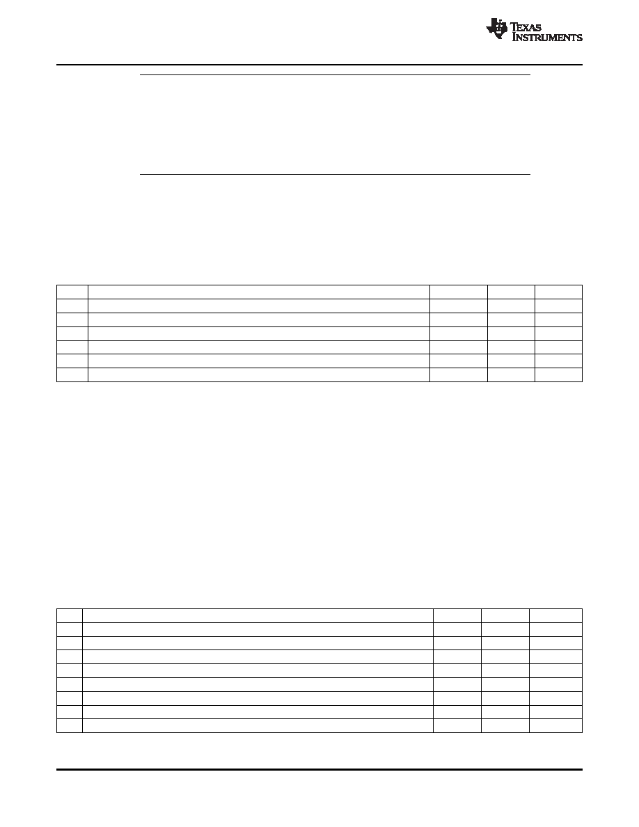
Bulk bypass capacitors are required for moderate speed bypassing of the DDR2 and other circuitry.
Table 6-33 contains the minimum numbers and capacitance required for the bulk bypass capacitors. This
table covers only the bypass needs of the DSP and DDR2 interfaces. Additional bulk bypass capacitance
may be needed for other circuitry.
Table 6-33. Bulk Bypass Capacitors
NO.
PARAMETER
MIN
MAX
UNIT
1
DVDD18 Bulk Bypass Capacitor Count
(1)
3
Devices
2
DVDD18 Bulk Bypass Total Capacitance
30
μF
3
DDR#1 Bulk Bypass Capacitor Count(2)
1
Devices
4
DDR#1 Bulk Bypass Total Capacitance
10
μF
5
DDR#2 Bulk Bypass Capacitor Count(2) (3)
1
Devices
6
DDR#2 Bulk Bypass Total Capacitance(3)
10
μF
(1)
These devices should be placed near the device they are bypassing, but preference should be given to the placement of the high-speed
(HS) bypass caps.
(2)
These devices should be placed near the device they are bypassing, but preference should be given to the placement of the high-speed
(HS) bypass caps.
(3)
Only used on 32-bit wide DDR2 memory systems
6.9.3.7
High-Speed Bypass Capacitors
High-Speed (HS) bypass capacitors are critical for proper DDR2 interface operation. It is particularly
important to minimize the parasitic series inductance of the HS bypass cap, DSP/DDR power, and
DSP/DDR ground connections. Table 6-34 contains the specification for the HS bypass capacitors as well
as for the power connections on the PCB.
6.9.3.8
Net Classes
Table 6-35 lists the clock net classes for the DDR2 interface. Table 6-36 lists the signal net classes, and
associated clock net classes, for the signals in the DDR2 interface. These net classes are used for the
termination and routing rules that follow.
Table 6-34. High-Speed Bypass Capacitors
NO.
PARAMETER
MIN
MAX
UNIT
1
HS Bypass Capacitor Package Size(1)
0402
10 Mils
2
Distance from HS bypass capacitor to device being bypassed
250
Mils
3
Number of connection vias for each HS bypass capacitor(2)
2
Vias
4
Trace length from bypass capacitor contact to connection via
1
30
Mils
5
Number of connection vias for each DDR2 device power or ground balls
1
Vias
6
Trace length from DDR2 device power ball to connection via
35
Mils
7
DVDD18 HS Bypass Capacitor Count
(3)
20
Devices
8
DVDD18 HS Bypass Capacitor Total Capacitance
1.2
μF
(1)
L × W, 10 mil units ( i.e., a 0402 is a 40 × 20 mil surface mount capacitor)
(2)
An additional HS bypass capacitor can share the connection vias only if it is mounted on the opposite side of the board.
(3)
These devices should be placed as close as possible to the device being bypassed.
106
Peripheral Information and Electrical Specifications
Copyright 2007–2012, Texas Instruments Incorporated
Product Folder Link(s): TMS320DM647 TMS320DM648
相关PDF资料 |
PDF描述 |
|---|---|
| EPM7512BBC256-10 | IC MAX 7000 CPLD 512 256-BGA |
| GNT424ABG | PWR SUP UNIV IMP 24VDC 16.7ADC |
| VE-2VT-CY-F4 | CONVERTER MOD DC/DC 6.5V 50W |
| GEM08DRSH | CONN EDGECARD 16POS DIP .156 SLD |
| RS-053.3D | CONV DC/DC 2W 4.5-9VIN +/-3.3V |
相关代理商/技术参数 |
参数描述 |
|---|---|
| TMS320DM648ZUTA6 | 功能描述:数字信号处理器和控制器 - DSP, DSC Digital Media Proc RoHS:否 制造商:Microchip Technology 核心:dsPIC 数据总线宽度:16 bit 程序存储器大小:16 KB 数据 RAM 大小:2 KB 最大时钟频率:40 MHz 可编程输入/输出端数量:35 定时器数量:3 设备每秒兆指令数:50 MIPs 工作电源电压:3.3 V 最大工作温度:+ 85 C 封装 / 箱体:TQFP-44 安装风格:SMD/SMT |
| TMS320DM648ZUTA8 | 功能描述:数字信号处理器和控制器 - DSP, DSC Digital Media Proc RoHS:否 制造商:Microchip Technology 核心:dsPIC 数据总线宽度:16 bit 程序存储器大小:16 KB 数据 RAM 大小:2 KB 最大时钟频率:40 MHz 可编程输入/输出端数量:35 定时器数量:3 设备每秒兆指令数:50 MIPs 工作电源电压:3.3 V 最大工作温度:+ 85 C 封装 / 箱体:TQFP-44 安装风格:SMD/SMT |
| TMS320DM648ZUTD1 | 功能描述:数字信号处理器和控制器 - DSP, DSC Digital Media Proc RoHS:否 制造商:Microchip Technology 核心:dsPIC 数据总线宽度:16 bit 程序存储器大小:16 KB 数据 RAM 大小:2 KB 最大时钟频率:40 MHz 可编程输入/输出端数量:35 定时器数量:3 设备每秒兆指令数:50 MIPs 工作电源电压:3.3 V 最大工作温度:+ 85 C 封装 / 箱体:TQFP-44 安装风格:SMD/SMT |
| TMS320DM648ZUTD7 | 功能描述:数字信号处理器和控制器 - DSP, DSC Digital Media Proc RoHS:否 制造商:Microchip Technology 核心:dsPIC 数据总线宽度:16 bit 程序存储器大小:16 KB 数据 RAM 大小:2 KB 最大时钟频率:40 MHz 可编程输入/输出端数量:35 定时器数量:3 设备每秒兆指令数:50 MIPs 工作电源电压:3.3 V 最大工作温度:+ 85 C 封装 / 箱体:TQFP-44 安装风格:SMD/SMT |
| TMS320DM648ZUTD9 | 功能描述:数字信号处理器和控制器 - DSP, DSC Digital Media Proc RoHS:否 制造商:Microchip Technology 核心:dsPIC 数据总线宽度:16 bit 程序存储器大小:16 KB 数据 RAM 大小:2 KB 最大时钟频率:40 MHz 可编程输入/输出端数量:35 定时器数量:3 设备每秒兆指令数:50 MIPs 工作电源电压:3.3 V 最大工作温度:+ 85 C 封装 / 箱体:TQFP-44 安装风格:SMD/SMT |
发布紧急采购,3分钟左右您将得到回复。