- 您现在的位置:买卖IC网 > PDF目录98281 > TPS40077PWPRG4 (TEXAS INSTRUMENTS INC) 2 A SWITCHING CONTROLLER, 1000 kHz SWITCHING FREQ-MAX, PDSO16 PDF资料下载
参数资料
| 型号: | TPS40077PWPRG4 |
| 厂商: | TEXAS INSTRUMENTS INC |
| 元件分类: | 稳压器 |
| 英文描述: | 2 A SWITCHING CONTROLLER, 1000 kHz SWITCHING FREQ-MAX, PDSO16 |
| 封装: | GREEN, PLASTIC, HTSSOP-16 |
| 文件页数: | 18/43页 |
| 文件大小: | 847K |
| 代理商: | TPS40077PWPRG4 |
第1页第2页第3页第4页第5页第6页第7页第8页第9页第10页第11页第12页第13页第14页第15页第16页第17页当前第18页第19页第20页第21页第22页第23页第24页第25页第26页第27页第28页第29页第30页第31页第32页第33页第34页第35页第36页第37页第38页第39页第40页第41页第42页第43页
f Frequency Hz
0
5
10
15
20
25
30
35
40
45
50
Gain
dB
Phase
°
Gain
Phase
100
1k
10k
1M
100k
200
180
160
140
120
100
80
40
0
G027
20
60
Component Selection
LOUT +
V
OUT
V
IN(max)
V
IN(max) * VOUT
fs
I
RIPPLE
(18)
I
LOUT_RMS +
I
OUT
2
)
I
RIPPLE
2
12
+ 10.02 A
(19)
I
PK + IOUT )
I
RIPPLE
2
+ 11.03 A
(20)
www.ti.com ..................................................................................................................................................... SLUS714D – JANUARY 2007 – REVISED APRIL 2009
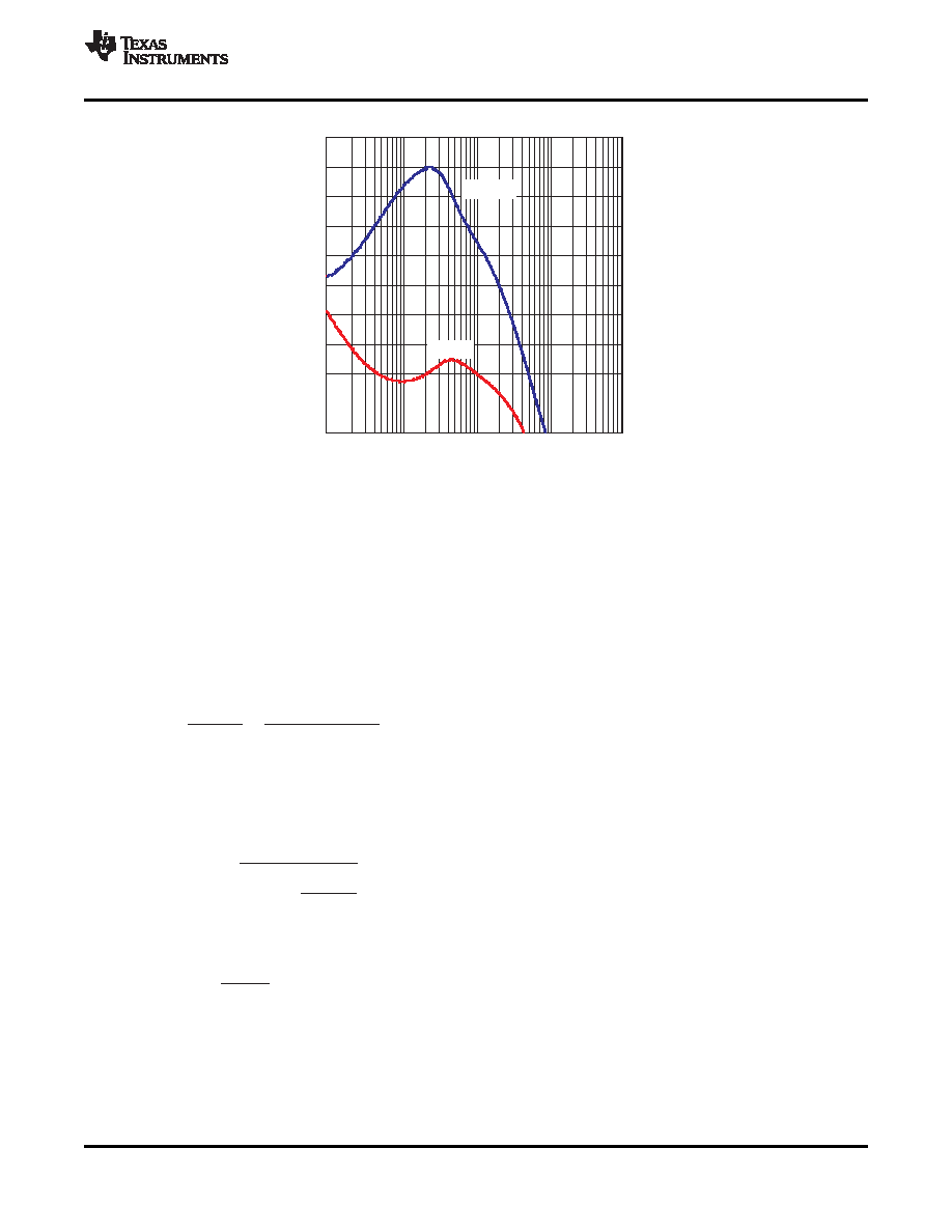
Figure 30. Bode Plot Showing 57° Phase Margin at Crossover Frequency of 54 kHz
Power Train Components
Output Inductor, LOUT
The output inductor is one of the most important components to select. It stores the energy necessary to keep
the output regulated when the switch FET is turned off. The value of the output inductor dictates the peak and
RMS currents in the converter. These currents are important when selecting other components. Equation (1) can
be used to calculate a value for LOUT for this module which operates at a switching frequency (f) of 300 kHz.
IRIPPLE is the allowable ripple in the inductor. Select IRIPPLE to be between 20% and 30% of maximum IOUT. For
this design, IRIPPLE of 2.5 A was selected. Calculated LOUT is 2.13 H. A standard inductor with value of 2.5 H
was chosen. This will reduce IRIPPLE by about 17% to 2.07 A.
This IRIPPLE value can be used calculate the rms and peak current flowing in LOUT. Note that this peak current is
also seen by the switching FET and synchronous rectifier.
The power loss from the selected inductor DCR is 357 mW. The ac core loss for this Coilcraft inductor may be
found from the Coilcraft Web site, where there is a loss calculator. The loss is 179 mW.
The inductor is selected with a saturation current higher than this current plus the current that is developed
charging the output capacitance during the soft-start interval.
Copyright 2007–2009, Texas Instruments Incorporated
25
Product Folder Link(s) :TPS40077
相关PDF资料 |
PDF描述 |
|---|---|
| TPS40077PWPG4 | 2 A SWITCHING CONTROLLER, 1000 kHz SWITCHING FREQ-MAX, PDSO16 |
| TPS40090QPWRQ1 | SWITCHING CONTROLLER, 1200 kHz SWITCHING FREQ-MAX, PDSO24 |
| TPS40101RGET | 1.3 A SWITCHING CONTROLLER, 1000 kHz SWITCHING FREQ-MAX, PQCC24 |
| TPS40131RHBT | SWITCHING CONTROLLER, 1200 kHz SWITCHING FREQ-MAX, PQCC32 |
| TPS40131RHBTG4 | SWITCHING CONTROLLER, 1200 kHz SWITCHING FREQ-MAX, PQCC32 |
相关代理商/技术参数 |
参数描述 |
|---|---|
| TPS40090 | 制造商:TI 制造商全称:Texas Instruments 功能描述:HIGH FREQUENCY MULTIPHASE CONTROLLER |
| TPS40090EVM-001 | 功能描述:电源管理IC开发工具 TPS40090-001 Eval Mod RoHS:否 制造商:Maxim Integrated 产品:Evaluation Kits 类型:Battery Management 工具用于评估:MAX17710GB 输入电压: 输出电压:1.8 V |
| TPS40090EVM-002 | 功能描述:电源管理IC开发工具 TPS40090-002 Eval Mod RoHS:否 制造商:Maxim Integrated 产品:Evaluation Kits 类型:Battery Management 工具用于评估:MAX17710GB 输入电压: 输出电压:1.8 V |
| TPS40090PW | 功能描述:DC/DC 开关控制器 4 Ch Multiphase Buck DC/DC Controller RoHS:否 制造商:Texas Instruments 输入电压:6 V to 100 V 开关频率: 输出电压:1.215 V to 80 V 输出电流:3.5 A 输出端数量:1 最大工作温度:+ 125 C 安装风格: 封装 / 箱体:CPAK |
| TPS40090PW | 制造商:Texas Instruments 功能描述:CONTROLLER IC |
发布紧急采购,3分钟左右您将得到回复。