- 您现在的位置:买卖IC网 > PDF目录98283 > TPS54623RHLT (TEXAS INSTRUMENTS INC) 15 A SWITCHING REGULATOR, 1760 kHz SWITCHING FREQ-MAX, PQCC14 PDF资料下载
参数资料
| 型号: | TPS54623RHLT |
| 厂商: | TEXAS INSTRUMENTS INC |
| 元件分类: | 稳压器 |
| 英文描述: | 15 A SWITCHING REGULATOR, 1760 kHz SWITCHING FREQ-MAX, PQCC14 |
| 封装: | 3.50 X 3.50 MM, GREEN, PLASTIC, QFN-14 |
| 文件页数: | 15/35页 |
| 文件大小: | 1468K |
| 代理商: | TPS54623RHLT |
第1页第2页第3页第4页第5页第6页第7页第8页第9页第10页第11页第12页第13页第14页当前第15页第16页第17页第18页第19页第20页第21页第22页第23页第24页第25页第26页第27页第28页第29页第30页第31页第32页第33页第34页第35页
f
-
=
×
Vinm ax
Vout
L1
Io Kind
Vinm ax
sw
f
-
=
×
Vinmax
Vout
Iripple
L1
Vinmax
sw
(
)
2
1
12
f
×
-
=
+
×
÷
÷
×
è
o
V
Vinmax
Vo
ILrms
Io
Vinmax L1
sw
2
=
+
Iripple
ILpeak
Iout
2
f
× D
>
× D
Iout
Co
sw
Vout
SLVSB09
– SEPTEMBER 2011
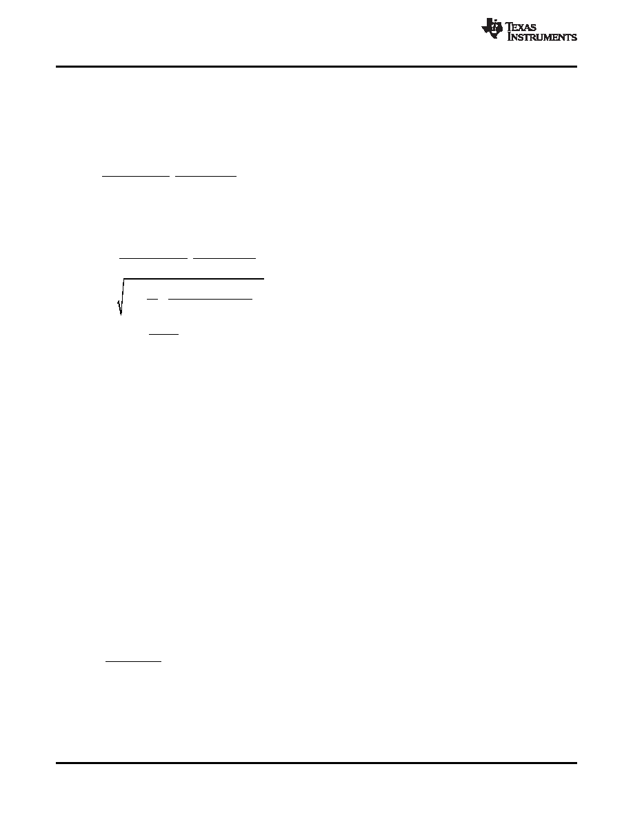
Output Inductor Selection
To calculate the value of the output inductor, use Equation 18. KIND is a coefficient that represents the amount
of inductor ripple current relative to the maximum output current. The inductor ripple current is filtered by the
output capacitor. Therefore, choosing high inductor ripple currents impact the selection of the output capacitor
since the output capacitor must have a ripple current rating equal to or greater than the inductor ripple current. In
general, the inductor ripple value is at the discretion of the designer; however, KIND is normally from 0.1 to 0.3
for the majority of applications.
(18)
For this design example, use KIND = 0.3 and the inductor value is calculated to be 3.08
H. For this design, a
nearest standard value was chosen: 3.3
H. For the output filter inductor, it is important that the RMS current
and saturation current ratings not be exceeded. The RMS and peak inductor current can be found from
(19)
(20)
(21)
For this design, the RMS inductor current is 6.02 A and the peak inductor current is 6.84 A. The chosen inductor
is a Coilcraft MSS1048 series 3.3
H. It has a saturation current rating of 7.38 A and a RMS current rating of
7.22 A.
The current flowing through the inductor is the inductor ripple current plus the output current. During power up,
faults or transient load conditions, the inductor current can increase above the calculated peak inductor current
level calculated above. In transient conditions, the inductor current can increase up to the switch current limit of
the device. For this reason, the most conservative approach is to specify an inductor with a saturation current
rating equal to or greater than the switch current limit rather than the peak inductor current.
Output Capacitor Selection
There are three primary considerations for selecting the value of the output capacitor. The output capacitor
determines the modulator pole, the output voltage ripple, and how the regulator responds to a large change in
load current. The output capacitance needs to be selected based on the more stringent of these three criteria
The desired response to a large change in the load current is the first criteria. The output capacitor needs to
supply the load with current when the regulator can not. This situation would occur if there are desired hold-up
times for the regulator where the output capacitor must hold the output voltage above a certain level for a
specified amount of time after the input power is removed. The regulator is also temporarily not able to supply
sufficient output current if there is a large, fast increase in the current needs of the load such as a transition from
no load to full load. The regulator usually needs two or more clock cycles for the control loop to see the change
in load current and output voltage and adjust the duty cycle to react to the change. The output capacitor must be
sized to supply the extra current to the load until the control loop responds to the load change. The output
capacitance must be large enough to supply the difference in current for 2 clock cycles while only allowing a
tolerable amount of droop in the output voltage. Equation 22 shows the minimum output capacitance necessary
to accomplish this.
(22)
Where
ΔIout is the change in output current, Fsw is the regulators switching frequency and ΔVout is the
allowable change in the output voltage. For this example, the transient load response is specified as a 5%
change in Vout for a load step of 1A. For this example,
ΔIout = 3.0 A and ΔVout = 0.05 x 3.3 = 0.165 V. Using
these numbers gives a minimum capacitance of 75.8
μF. This value does not take the ESR of the output
capacitor into account in the output voltage change. For ceramic capacitors, the ESR is usually small enough to
ignore in this calculation.
22
Copyright
2011, Texas Instruments Incorporated
Product Folder Link(s) :TPS54623
相关PDF资料 |
PDF描述 |
|---|---|
| TPS54672PWPG4 | 12 A SWITCHING REGULATOR, 700 kHz SWITCHING FREQ-MAX, PDSO28 |
| TPS54810PWPRG4 | 12 A SWITCHING REGULATOR, 762 kHz SWITCHING FREQ-MAX, PDSO28 |
| TPS54810PWPG4 | 12 A SWITCHING REGULATOR, 762 kHz SWITCHING FREQ-MAX, PDSO28 |
| TPS54873PWPG4 | 12 A SWITCHING REGULATOR, 762 kHz SWITCHING FREQ-MAX, PDSO28 |
| TPS54880PWPR | 12 A SWITCHING REGULATOR, 762 kHz SWITCHING FREQ-MAX, PDSO28 |
相关代理商/技术参数 |
参数描述 |
|---|---|
| TPS54625EVM-608 | 制造商:Texas Instruments 功能描述:TPS54625EVM-608 - Boxed Product (Development Kits) 制造商:Texas Instruments 功能描述:TPS54625 EVAL MOD |
| TPS54625PWP | 制造商:Texas Instruments 功能描述: 制造商:Texas Instruments 功能描述:IC REG BUCK ADJ 6.5A 14HTSSOP 制造商:Texas Instruments 功能描述:IC SYNC STEP DOWN 650KHZ HT |
| TPS54625PWPR | 功能描述:Buck Switching Regulator IC Positive Adjustable 0.765V 1 Output 6.5A 14-TSSOP (0.173", 4.40mm Width) Exposed Pad 制造商:texas instruments 系列:D-CAP2?? 包装:剪切带(CT) 零件状态:有效 功能:降压 输出配置:正 拓扑:降压 输出类型:可调式 输出数:1 电压 - 输入(最小值):4.5V 电压 - 输入(最大值):18V 电压 - 输出(最小值/固定):0.765V 电压 - 输出(最大值):5.5V 电流 - 输出:6.5A 频率 - 开关:650kHz 同步整流器:是 工作温度:-40°C ~ 85°C(TA) 安装类型:表面贴装 封装/外壳:14-TSSOP(0.173",4.40mm 宽)裸焊盘 供应商器件封装:14-HTSSOP 标准包装:1 |
| TPS54626EVM-608 | 制造商:Texas Instruments 功能描述:TPS54626EVM-608 - Boxed Product (Development Kits) 制造商:Texas Instruments 功能描述:TPS54626 EVAL MOD |
| TPS54626PWP | 制造商:Texas Instruments 功能描述: 制造商:Texas Instruments 功能描述:IC SYNC STEP DOWN 650KHZ HT 制造商:Texas Instruments 功能描述:18V 6.5A DCAP2 sync converter |
发布紧急采购,3分钟左右您将得到回复。