- 您现在的位置:买卖IC网 > PDF目录98283 > TPS54623RHLT (TEXAS INSTRUMENTS INC) 15 A SWITCHING REGULATOR, 1760 kHz SWITCHING FREQ-MAX, PQCC14 PDF资料下载
参数资料
| 型号: | TPS54623RHLT |
| 厂商: | TEXAS INSTRUMENTS INC |
| 元件分类: | 稳压器 |
| 英文描述: | 15 A SWITCHING REGULATOR, 1760 kHz SWITCHING FREQ-MAX, PQCC14 |
| 封装: | 3.50 X 3.50 MM, GREEN, PLASTIC, QFN-14 |
| 文件页数: | 18/35页 |
| 文件大小: | 1468K |
| 代理商: | TPS54623RHLT |
第1页第2页第3页第4页第5页第6页第7页第8页第9页第10页第11页第12页第13页第14页第15页第16页第17页当前第18页第19页第20页第21页第22页第23页第24页第25页第26页第27页第28页第29页第30页第31页第32页第33页第34页第35页
2
f
p
=
×
Iout
pmod
Vout Cout
1
2
f
p
=
×
zm od
RESR Cout
f
=
×
co
pmod
zmod
2
f
=
×
sw
co
pmod
2
f
p ×
×
=
×
ea
ps
c Vout Cout
R4
gm
Vref gm
×
=
×
Vout Cout
C4
Iout R4
×
=
RESR Cout
C5
R4
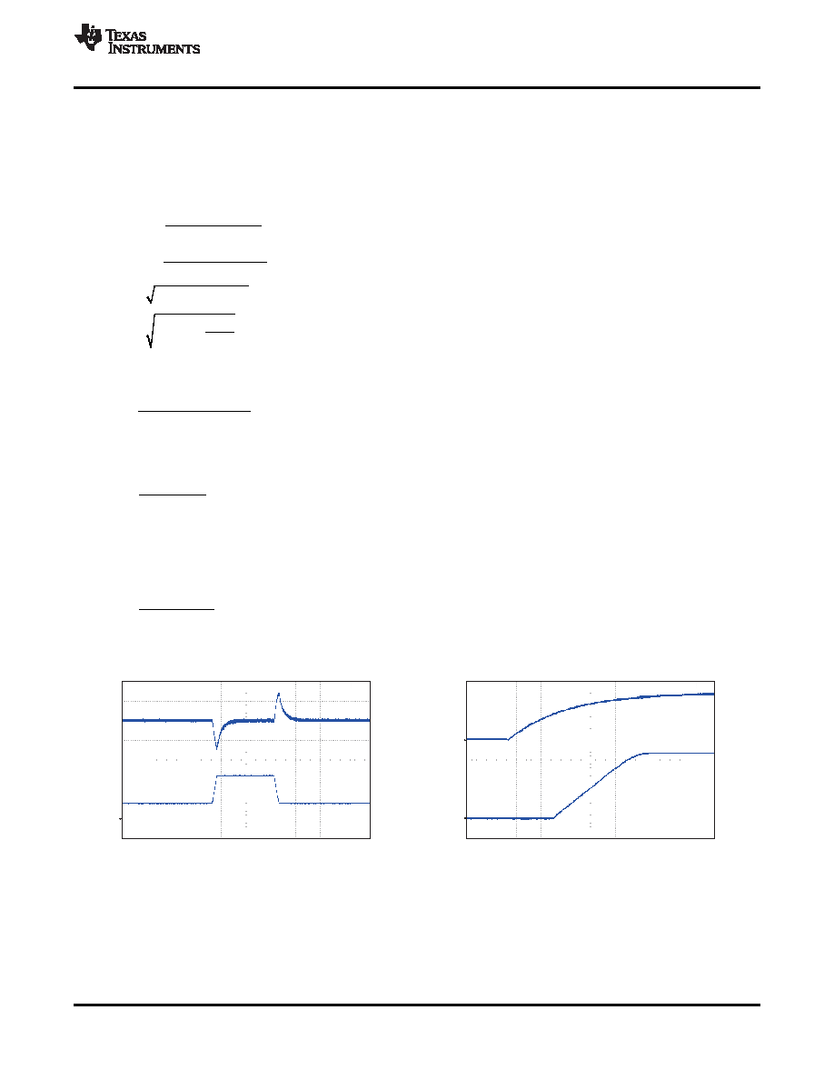
V = 5 V / div
IN
V
= 1 V / div
OUT
Time = 2 msec / div
V
= 100 mV / div (dc coupled, -3.13 V offset)
OUT
I
= 2 A / div
OUT
Load step = 1.5 A to 4.5 A Slew rate = 100 mA / sec
Time = 200 sec / div
SLVSB09
– SEPTEMBER 2011
For Cout, use a derated value of 75
F. use Equation 33 and Equation 34 to estimate a starting point for the
closed loop crossover frequency fco. Then the required compensation components may be derived. For this
design example, fpmod is 3.86 kHz and fzmod is 707.4 kHz. Equation 33 is the geometric mean of the modulator
pole and the esr zero and Equation 34 is the geometric mean of the modulator pole and one half the switching
frequency. Use a frequency near the lower of these two values as the intended crossover frequency fco. In this
case Equation 33 yields 52.2 kHz and Equation 34 yields 30.4 kHz. The lower value is 30.4 kHz. A slightly higher
frequency of 30 kHz is chosen as the intended crossover frequency.
(31)
(32)
(33)
(34)
Now the compensation components can be calculated. First calculate the value for R2 which sets the gain of the
compensated network at the crossover frequency. Use Equation 35 to determine the value of R2.
(35)
Next calculate the value of C3. Together with R2, C3 places a compensation zero at the modulator pole
frequency. Equation 36 to determine the value of C3.
(36)
Using Equation 35 and Equation 36 the standard values for R4 and C4 are 3.74 k
and 0.01 F.
An additional high frequency pole can be used if necessary by adding a capacitor in parallel with the series
combination of R4 and C4. The pole frequency can be placed at the ESR zero frequency of the output cpacitor
as given by Equation 13. Use Equation 37 to calculate the required capacitor value for C5.
(37)
Application Curves
LOAD TRANSIENT
STARTUP with VIN
Figure 32.
Figure 33.
Copyright
2011, Texas Instruments Incorporated
25
Product Folder Link(s) :TPS54623
相关PDF资料 |
PDF描述 |
|---|---|
| TPS54672PWPG4 | 12 A SWITCHING REGULATOR, 700 kHz SWITCHING FREQ-MAX, PDSO28 |
| TPS54810PWPRG4 | 12 A SWITCHING REGULATOR, 762 kHz SWITCHING FREQ-MAX, PDSO28 |
| TPS54810PWPG4 | 12 A SWITCHING REGULATOR, 762 kHz SWITCHING FREQ-MAX, PDSO28 |
| TPS54873PWPG4 | 12 A SWITCHING REGULATOR, 762 kHz SWITCHING FREQ-MAX, PDSO28 |
| TPS54880PWPR | 12 A SWITCHING REGULATOR, 762 kHz SWITCHING FREQ-MAX, PDSO28 |
相关代理商/技术参数 |
参数描述 |
|---|---|
| TPS54625EVM-608 | 制造商:Texas Instruments 功能描述:TPS54625EVM-608 - Boxed Product (Development Kits) 制造商:Texas Instruments 功能描述:TPS54625 EVAL MOD |
| TPS54625PWP | 制造商:Texas Instruments 功能描述: 制造商:Texas Instruments 功能描述:IC REG BUCK ADJ 6.5A 14HTSSOP 制造商:Texas Instruments 功能描述:IC SYNC STEP DOWN 650KHZ HT |
| TPS54625PWPR | 功能描述:Buck Switching Regulator IC Positive Adjustable 0.765V 1 Output 6.5A 14-TSSOP (0.173", 4.40mm Width) Exposed Pad 制造商:texas instruments 系列:D-CAP2?? 包装:剪切带(CT) 零件状态:有效 功能:降压 输出配置:正 拓扑:降压 输出类型:可调式 输出数:1 电压 - 输入(最小值):4.5V 电压 - 输入(最大值):18V 电压 - 输出(最小值/固定):0.765V 电压 - 输出(最大值):5.5V 电流 - 输出:6.5A 频率 - 开关:650kHz 同步整流器:是 工作温度:-40°C ~ 85°C(TA) 安装类型:表面贴装 封装/外壳:14-TSSOP(0.173",4.40mm 宽)裸焊盘 供应商器件封装:14-HTSSOP 标准包装:1 |
| TPS54626EVM-608 | 制造商:Texas Instruments 功能描述:TPS54626EVM-608 - Boxed Product (Development Kits) 制造商:Texas Instruments 功能描述:TPS54626 EVAL MOD |
| TPS54626PWP | 制造商:Texas Instruments 功能描述: 制造商:Texas Instruments 功能描述:IC SYNC STEP DOWN 650KHZ HT 制造商:Texas Instruments 功能描述:18V 6.5A DCAP2 sync converter |
发布紧急采购,3分钟左右您将得到回复。