- 您现在的位置:买卖IC网 > PDF目录68419 > TPS62650YFFR (TEXAS INSTRUMENTS INC) 1.7 A SWITCHING REGULATOR, 6600 kHz SWITCHING FREQ-MAX, BGA9 PDF资料下载
参数资料
| 型号: | TPS62650YFFR |
| 厂商: | TEXAS INSTRUMENTS INC |
| 元件分类: | 稳压器 |
| 英文描述: | 1.7 A SWITCHING REGULATOR, 6600 kHz SWITCHING FREQ-MAX, BGA9 |
| 封装: | GREEN, DSBGA-9 |
| 文件页数: | 15/38页 |
| 文件大小: | 820K |
| 代理商: | TPS62650YFFR |
第1页第2页第3页第4页第5页第6页第7页第8页第9页第10页第11页第12页第13页第14页当前第15页第16页第17页第18页第19页第20页第21页第22页第23页第24页第25页第26页第27页第28页第29页第30页第31页第32页第33页第34页第35页第36页第37页第38页
SLVS808A
– AUGUST 2009 – REVISED FEBRUARY 2011
UNDERVOLTAGE LOCKOUT
The undervoltage lockout circuit prevents the device from misoperation at low input voltages. It prevents the
converter from turning on the switch or rectifier MOSFET under undefined conditions. The TPS6265x device
have a UVLO threshold set to 2.05V (typical). Fully functional operation is permitted down to 2.15 V input
voltage.
SHORT-CIRCUIT PROTECTION
The TPS6265x integrates a P-channel MOSFET current limit to protect the device against heavy load or short
circuits. When the current in the P-channel MOSFET reaches its current limit, the P-channel MOSFET is turned
off and the N-channel MOSFET is turned on. The regulator continues to limit the current on a cycle-by-cycle
basis.
As soon as the output voltage falls below ca. 0.4V, the converter current limit is reduced to half of the nominal
value and the PWROK bit is reset. Because the short-circuit protection is enabled during start-up, the device
does not deliver more than half of its nominal current limit until the output voltage exceeds approximately 0.5V.
This needs to be considered when a load acting as a current sink is connected to the output of the converter.
THERMAL SHUTDOWN
As soon as the junction temperature, TJ, exceeds typically 140°C, the device goes into thermal shutdown. In this
mode, the P- and N-channel MOSFETs are turned off. The device continues its operation when the junction
temperature again falls below typically 130
°C.
VOLTAGE AND MODE SELECTION
The TPS6265x features a pin-selectable output voltage. VSEL is primarily used to scale the output voltage
between active (VSEL = HIGH) and sleep mode (VSEL = LOW). For maximum flexibility, it is possible to
reprogram the operating mode of the converter (e.g. forced PWM, or auto transition PFM/PWM) associated with
VSEL signal via the I2C interface
VSEL output voltage and mode selection is defined as following:
VSEL = LOW:
–– DC/DC output voltage determined by VSEL0 register value. DC/DC mode of operation is
determined by MODE0 bit in CONTROL1 register.
VSEL = HIGH:
–– DC/DC output voltage determined by VSEL1 register value. DC/DC mode of operation is
determined by MODE1 bit in CONTROL1 register.
The application processor programs via I2C the output voltages associated with the two states of VSEL signal:
floor (VSEL0) and roof (VSEL1) values. The application processor also writes the DEFSLEW value in the
CONTROL2 register to control the output voltage ramp rate.
These two registers can be continuously updated via I2C to provide the appropriate output voltage according to
the VSEL input. The voltage changes with the selected ramp rate immediately after writing to the VSEL0 or
VSEL1 register.
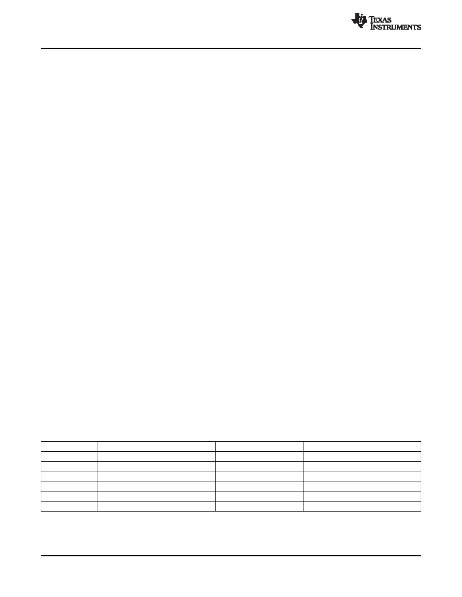
Table 1 shows the output voltage states depending on VSEL0, VSEL1 registers, and VSEL signal.
Table 1. Dynamic Voltage Scaling Functional Overview
VSEL PIN
VSEL0 REGISTER
VSEL1 REGISTER
OUTPUT VOLTAGE
Low
No action
Floor
Low
Write new value
No action
Change to new value
Low
No action
Write
No change stays at floor voltage
High
No action
Roof
High
Write new value
No action
No change stays at roof voltage
High
No action
Write new value
Change to new value
22
2009–2011, Texas Instruments Incorporated
相关PDF资料 |
PDF描述 |
|---|---|
| TPS62650YFF | 1.7 A SWITCHING REGULATOR, 6600 kHz SWITCHING FREQ-MAX, BGA9 |
| TPS62731DRYR | SWITCHING REGULATOR, 3000 kHz SWITCHING FREQ-MAX, PDSO6 |
| TPS62730DRY | SWITCHING REGULATOR, 3000 kHz SWITCHING FREQ-MAX, PDSO6 |
| TPS62732DRYT | SWITCHING REGULATOR, 3000 kHz SWITCHING FREQ-MAX, PDSO6 |
| TPS62732DRY | SWITCHING REGULATOR, 3000 kHz SWITCHING FREQ-MAX, PDSO6 |
相关代理商/技术参数 |
参数描述 |
|---|---|
| TPS62650YFFT | 功能描述:直流/直流开关转换器 800mA 6MHz Synch Step-Down Converter RoHS:否 制造商:STMicroelectronics 最大输入电压:4.5 V 开关频率:1.5 MHz 输出电压:4.6 V 输出电流:250 mA 输出端数量:2 最大工作温度:+ 85 C 安装风格:SMD/SMT |
| TPS62651YFFR | 功能描述:直流/直流开关转换器 800mA,6MHz High Eff Step-Down Converter RoHS:否 制造商:STMicroelectronics 最大输入电压:4.5 V 开关频率:1.5 MHz 输出电压:4.6 V 输出电流:250 mA 输出端数量:2 最大工作温度:+ 85 C 安装风格:SMD/SMT |
| TPS62651YFFT | 功能描述:直流/直流开关转换器 800mA,6MHz High Eff Step-Down Converter RoHS:否 制造商:STMicroelectronics 最大输入电压:4.5 V 开关频率:1.5 MHz 输出电压:4.6 V 输出电流:250 mA 输出端数量:2 最大工作温度:+ 85 C 安装风格:SMD/SMT |
| TPS62660EVM-419 | 功能描述:电源管理IC开发工具 TPS62660 Eval Mod RoHS:否 制造商:Maxim Integrated 产品:Evaluation Kits 类型:Battery Management 工具用于评估:MAX17710GB 输入电压: 输出电压:1.8 V |
| TPS62660YFFR | 功能描述:直流/直流开关转换器 1000mA,6MHz Synch Step-Down Converter RoHS:否 制造商:STMicroelectronics 最大输入电压:4.5 V 开关频率:1.5 MHz 输出电压:4.6 V 输出电流:250 mA 输出端数量:2 最大工作温度:+ 85 C 安装风格:SMD/SMT |
发布紧急采购,3分钟左右您将得到回复。