- 您现在的位置:买卖IC网 > PDF目录69520 > TPS62660YFFR (TEXAS INSTRUMENTS INC) 1.75 A SWITCHING REGULATOR, 6600 kHz SWITCHING FREQ-MAX, BGA6 PDF资料下载
参数资料
| 型号: | TPS62660YFFR |
| 厂商: | TEXAS INSTRUMENTS INC |
| 元件分类: | 稳压器 |
| 英文描述: | 1.75 A SWITCHING REGULATOR, 6600 kHz SWITCHING FREQ-MAX, BGA6 |
| 封装: | GREEN, DSBGA-6 |
| 文件页数: | 12/30页 |
| 文件大小: | 791K |
| 代理商: | TPS62660YFFR |
第1页第2页第3页第4页第5页第6页第7页第8页第9页第10页第11页当前第12页第13页第14页第15页第16页第17页第18页第19页第20页第21页第22页第23页第24页第25页第26页第27页第28页第29页第30页
SLVS871B – FEBRUARY 2010 – REVISED SEPTEMBER 2010
www.ti.com
These devices have limited built-in ESD protection. The leads should be shorted together or the device placed in conductive foam
during storage or handling to prevent electrostatic damage to the MOS gates.
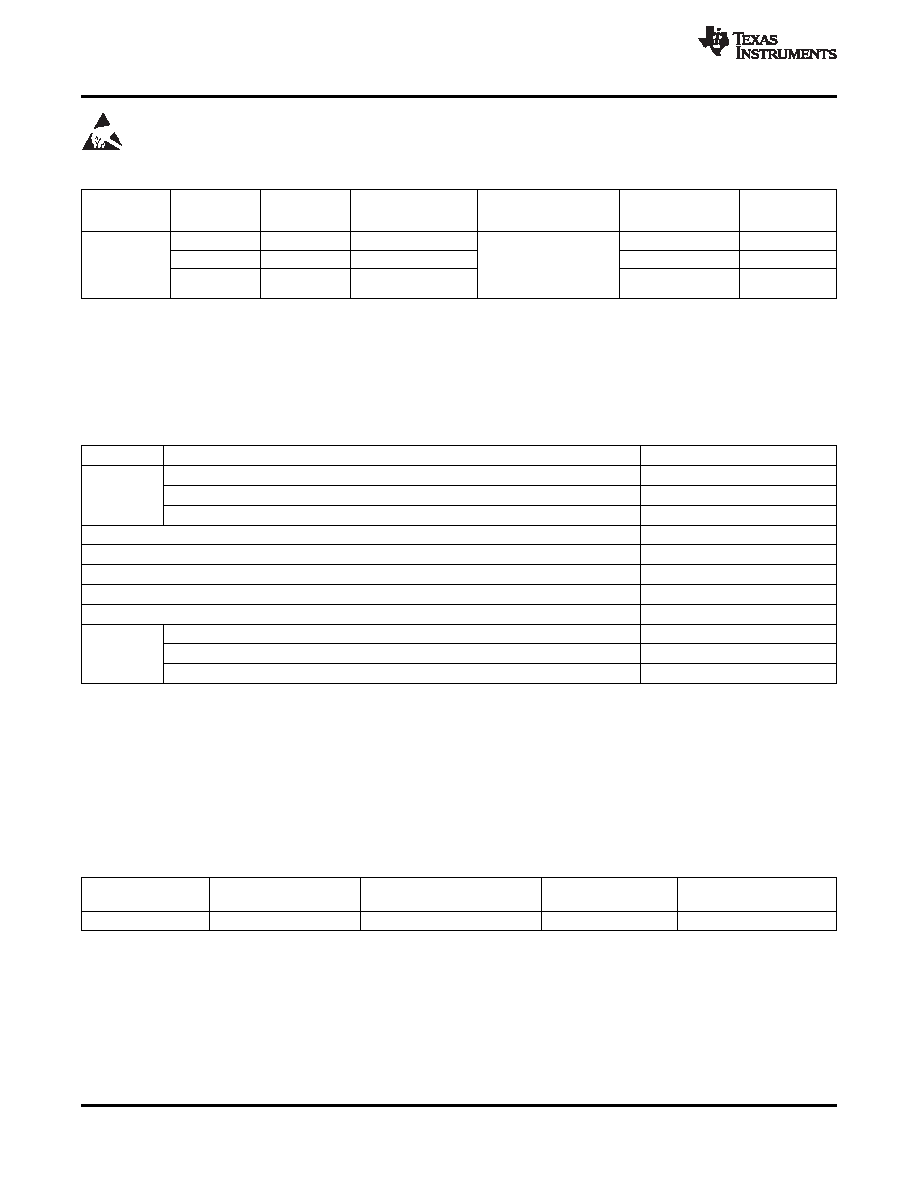
ORDERING INFORMATION(1)
PACKAGE
PART
OUTPUT
DEVICE
TA
PACKAGE
ORDERING(2) (3)
MARKING
NUMBER
VOLTAGE
SPECIFIC FEATURE
CHIP CODE
TPS62660
1.8V
TPS62660YFF
OO
TPS62661(4)
1.8V
Fast start-up time
-40°C to 85°C
YFF-6
Output capacitor
TPS62665
1.2V
TPS62665YFF
RS
discharge
(1)
For the most current package and ordering information, see the Package Option Addendum at the end of this document, or see the TI
website at www.ti.com.
(2)
The YFF package is available in tape and reel. Add an R suffix (TPS62660YFFR) to order quantities of 3000 parts. Add a T suffix
(TPS62660YFFT) to order quantities of 250 parts.
(3)
Internal tap points are available to facilitate output voltages in 25mV increments.
(4)
Product preview.
ABSOLUTE MAXIMUM RATINGS
over operating free-air temperature range (unless otherwise noted)
(1)
UNIT
Voltage at VIN, SW(2)
–0.3 V to 7 V
VI
Voltage at FB(2)
–0.3 V to 3.6 V
Voltage at EN, MODE (2)
–0.3 V to VI + 0.3 V
IO
Peak output current
1000 mA
Power dissipation
Internally limited
TA
Operating temperature range(3)
–40°C to 85°C
TJ (max)
Maximum operating junction temperature
150°C
Tstg
Storage temperature range
–65°C to 150°C
Human body model
2 kV
ESD rating (4) Charge device model
1 kV
Machine model
200 V
(1)
Stresses beyond those listed under absolute maximum ratings may cause permanent damage to the device. These are stress ratings
only and functional operation of the device at these or any other conditions beyond those indicated under recommended operating
conditions is not implied. Exposure to absolute-maximum-rated conditions for extended periods may affect device reliability.
(2)
All voltage values are with respect to network ground terminal.
(3)
In applications where high power dissipation and/or poor package thermal resistance is present, the maximum ambient temperature may
have to be derated. Maximum ambient temperature (TA(max)) is dependent on the maximum operating junction temperature (TJ(max)), the
maximum power dissipation of the device in the application (PD(max)), and the junction-to-ambient thermal resistance of the part/package
in the application (qJA), as given by the following equation: TA(max)= TJ(max)–(qJA X PD(max)). To achieve optimum performance, it is
recommended to operate the device with a maximum junction temperature of 105°C.
(4)
The human body model is a 100-pF capacitor discharged through a 1.5-k
resistor into each pin. The machine model is a 200-pF
capacitor discharged directly into each pin.
DISSIPATION RATINGS
(1)
POWER RATING
DERATING FACTOR
PACKAGE
RqJA
(2)
RqJB
(2)
TA ≤ 25°C
ABOVE TA = 25°C
YFF-6
125°C/W
53°C/W
800mW
8mW/°C
(1)
Maximum power dissipation is a function of TJ(max), qJA and TA. The maximum allowable power dissipation at any allowable ambient
temperature is PD = [TJ(max)-TA] / qJA.
(2)
This thermal data is measured with high-K board (4 layers board according to JESD51-7 JEDEC standard).
2
Copyright 2010, Texas Instruments Incorporated
相关PDF资料 |
PDF描述 |
|---|---|
| TPS62661YFFT | 1.75 A SWITCHING REGULATOR, 6600 kHz SWITCHING FREQ-MAX, BGA6 |
| TPS62660YFFT | 1.75 A SWITCHING REGULATOR, 6600 kHz SWITCHING FREQ-MAX, BGA6 |
| TPS62700YZF | 1.2 A SWITCHING REGULATOR, 2300 kHz SWITCHING FREQ-MAX, BGA8 |
| TPS62701YZFR | 1.2 A SWITCHING REGULATOR, 2300 kHz SWITCHING FREQ-MAX, BGA8 |
| TPS63001DRCTG4 | 2 A SWITCHING REGULATOR, 1500 kHz SWITCHING FREQ-MAX, PDSO10 |
相关代理商/技术参数 |
参数描述 |
|---|---|
| TPS62660YFFT | 功能描述:直流/直流开关转换器 1000mA,6MHz Synch Step-Down Converter RoHS:否 制造商:STMicroelectronics 最大输入电压:4.5 V 开关频率:1.5 MHz 输出电压:4.6 V 输出电流:250 mA 输出端数量:2 最大工作温度:+ 85 C 安装风格:SMD/SMT |
| TPS62665YFFR | 功能描述:直流/直流开关转换器 1000mA6MHz Synch Step-Down Converter RoHS:否 制造商:STMicroelectronics 最大输入电压:4.5 V 开关频率:1.5 MHz 输出电压:4.6 V 输出电流:250 mA 输出端数量:2 最大工作温度:+ 85 C 安装风格:SMD/SMT |
| TPS62665YFFT | 功能描述:直流/直流开关转换器 1000mA6MHz Synch Step-Down Converter RoHS:否 制造商:STMicroelectronics 最大输入电压:4.5 V 开关频率:1.5 MHz 输出电压:4.6 V 输出电流:250 mA 输出端数量:2 最大工作温度:+ 85 C 安装风格:SMD/SMT |
| TPS62671YFDR | 功能描述:直流/直流开关转换器 500mA,6MHz Hi-Eff Step-Down Converter RoHS:否 制造商:STMicroelectronics 最大输入电压:4.5 V 开关频率:1.5 MHz 输出电压:4.6 V 输出电流:250 mA 输出端数量:2 最大工作温度:+ 85 C 安装风格:SMD/SMT |
| TPS62671YFDT | 功能描述:直流/直流开关转换器 500mA,6MHz Hi-Eff Step-Down Converter RoHS:否 制造商:STMicroelectronics 最大输入电压:4.5 V 开关频率:1.5 MHz 输出电压:4.6 V 输出电流:250 mA 输出端数量:2 最大工作温度:+ 85 C 安装风格:SMD/SMT |
发布紧急采购,3分钟左右您将得到回复。