- 您现在的位置:买卖IC网 > PDF目录69523 > TPS84410RKGT (TEXAS INSTRUMENTS INC) 4 A SWITCHING REGULATOR, 600 kHz SWITCHING FREQ-MAX, PQCC39 PDF资料下载
参数资料
| 型号: | TPS84410RKGT |
| 厂商: | TEXAS INSTRUMENTS INC |
| 元件分类: | 稳压器 |
| 英文描述: | 4 A SWITCHING REGULATOR, 600 kHz SWITCHING FREQ-MAX, PQCC39 |
| 封装: | 9 X 11 MM, 2.80 MM HEIGHT, GREEN, PLASTIC, BQFN-39 |
| 文件页数: | 8/26页 |
| 文件大小: | 819K |
| 代理商: | TPS84410RKGT |
SLVSAR5
– SEPTEMBER 2011
Power Good (PWRGD)
The PWRGD pin is an open drain output. Once the voltage on the SENSE+ pin is between 93% and 105% of the
set voltage, the PWRGD pin pull-down is released and the pin floats. The recommended pull-up resistor value is
between 10 k
Ω and 100 kΩ to a voltage source that is 6 V or less. The PWRGD pin is in a defined state once
VIN is greater than 1.2 V, but with reduced current sinking capability. The PWRGD pin achieves full current
sinking capability once the VIN pin is above 2.95V. Figure 21 shows the PWRGD waveform during power-up.
The PWRGD pin is pulled low when the voltage on SENSE+ is lower than 91% or greater than 107% of the
nominal set voltage. Also, the PWRGD pin is pulled low if the input UVLO or thermal shutdown is asserted, or if
the INH pin is pulled low.
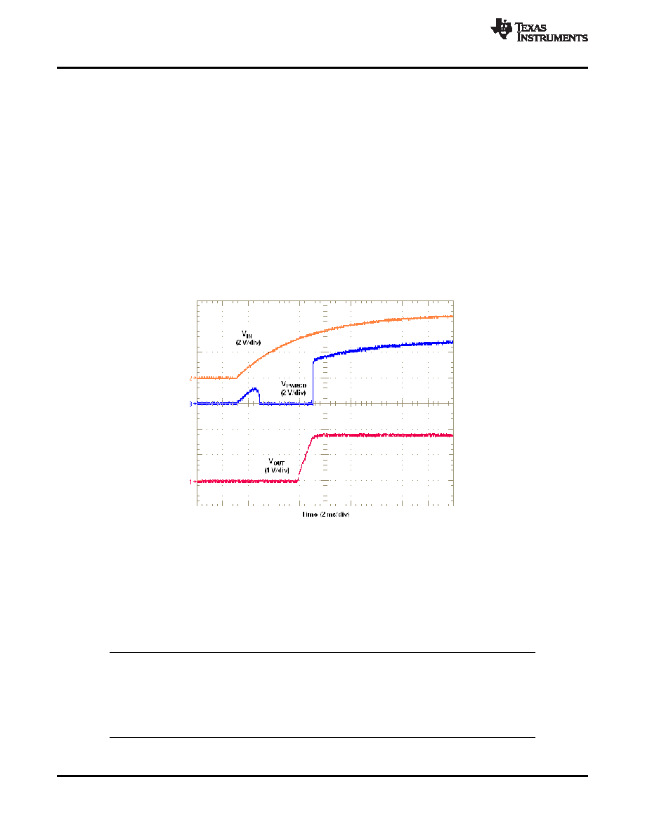
Power-Up Characteristics
When configured as shown in the front page schematic, the TPS84410 produces a regulated output voltage
following the application of a valid input voltage. During the power-up, internal soft-start circuitry slows the rate
that the output voltage rises, thereby limiting the amount of in-rush current that can be drawn from the input
source. The soft-start circuitry introduces a short time delay from the point that a valid input voltage is
recognized. Figure 21 shows the start-up waveforms for a TPS84410, operating from a 5-V input and with the
output voltage adjusted to 1.8 V. The waveform is measured with a 2-A constant current load.
Figure 21. Start-Up Waveforms
Remote Sense
The SENSE+ pin must be connected to VOUT at the load, or at the device pins.
Connecting the SENSE+ pin to VOUT at the load improves the load regulation performance of the device by
allowing it to compensate for any I-R voltage drop between its output pins and the load. An I-R drop is caused by
the high output current flowing through the small amount of pin and trace resistance. This should be limited to a
maximum of 300 mV.
NOTE
The remote sense feature is not designed to compensate for the forward drop of nonlinear
or frequency dependent components that may be placed in series with the converter
output. Examples include OR-ing diodes, filter inductors, ferrite beads, and fuses. When
these components are enclosed by the SENSE+ connection, they are effectively placed
inside the regulation control loop, which can adversely affect the stability of the regulator.
16
Copyright
2011, Texas Instruments Incorporated
相关PDF资料 |
PDF描述 |
|---|---|
| TPS84410RKGR | 4 A SWITCHING REGULATOR, 600 kHz SWITCHING FREQ-MAX, PQCC39 |
| TQN25A48S12 | 1-OUTPUT 300 W DC-DC REG PWR SUPPLY MODULE |
| TQN25A48S12 | 1-OUTPUT 300 W DC-DC REG PWR SUPPLY MODULE |
| TQN20A48S12 | 1-OUTPUT 240 W DC-DC REG PWR SUPPLY MODULE |
| TRF2020PW | PLL FREQUENCY SYNTHESIZER, 1200 MHz, PDSO24 |
相关代理商/技术参数 |
参数描述 |
|---|---|
| TPS844F | 制造商:TOSHIBA 制造商全称:Toshiba Semiconductor 功能描述:Silicon Epitaxial Planar |
| TPS84610 | 制造商:TI 制造商全称:Texas Instruments 功能描述:2.95-V to 6-V Input, 6-A Synchronous Buck, Integrated Power Solution |
| TPS84610EVM-003 | 功能描述:电源管理IC开发工具 TPS84610 Eval Mod RoHS:否 制造商:Maxim Integrated 产品:Evaluation Kits 类型:Battery Management 工具用于评估:MAX17710GB 输入电压: 输出电压:1.8 V |
| TPS84610RKG | 制造商:TI 制造商全称:Texas Instruments 功能描述:2-A to 6-A Integrated Power Solution |
| TPS84610RKGR | 功能描述:直流/直流开关转换器 3-6Vin,6A Sync Buck Integr Pwr Sol RoHS:否 制造商:STMicroelectronics 最大输入电压:4.5 V 开关频率:1.5 MHz 输出电压:4.6 V 输出电流:250 mA 输出端数量:2 最大工作温度:+ 85 C 安装风格:SMD/SMT |
发布紧急采购,3分钟左右您将得到回复。