- 您现在的位置:买卖IC网 > PDF目录69524 > TRF3761-BIRHAT (TEXAS INSTRUMENTS INC) PLL FREQUENCY SYNTHESIZER, 104 MHz, PQCC40 PDF资料下载
参数资料
| 型号: | TRF3761-BIRHAT |
| 厂商: | TEXAS INSTRUMENTS INC |
| 元件分类: | PLL合成/DDS/VCOs |
| 英文描述: | PLL FREQUENCY SYNTHESIZER, 104 MHz, PQCC40 |
| 封装: | GREEN, PLASTIC, MO-220VJJD-2, QFN-40 |
| 文件页数: | 31/60页 |
| 文件大小: | 1736K |
| 代理商: | TRF3761-BIRHAT |
第1页第2页第3页第4页第5页第6页第7页第8页第9页第10页第11页第12页第13页第14页第15页第16页第17页第18页第19页第20页第21页第22页第23页第24页第25页第26页第27页第28页第29页第30页当前第31页第32页第33页第34页第35页第36页第37页第38页第39页第40页第41页第42页第43页第44页第45页第46页第47页第48页第49页第50页第51页第52页第53页第54页第55页第56页第57页第58页第59页第60页
1.2 V
22.168
I
=
× (N + 1) ×
CP
R
8
bias1
(1)
(
)
3.3252 ×
N + 1
I
=
CP
Rbias1
(2)
www.ti.com ............................................................................................................................................... SLWS181J – OCTOBER 2005 – REVISED AUGUST 2008
OUT_MODE<1,0>: TRF3761 has an optional divide by 2 or 4 output, which is selectable by programming bits
<OUT_MODE_1, OUT_MODE_0> of register 1 (see Table 1).
CP_TEST: By setting bit DB30 to 1 it is possible to test the PFD up or down pulses. Internal TI use only.
TRIS_CP: If bit DB29 is set to 1, the charge pump output goes in tri-state. For normal operation, DB29 must be
set to 0.
ABPW: Bits <DB27, DB26> are used to program the width of the anti-backlash pulses of the PFD. The user
selects one of the following values: 0.9ns, 1.5ns, 2.7ns and 3.8ns. Backlash can occur when Fpfd becomes
phase aligned with Fout of the VCO. This will cause a high impedance state on the phase detector and allow the
output frequency to drift until the phase difference is enough to cause the phase detector to start sending signals
to the charge pump to correct the difference. This slight variation will show up as a sub harmonic of the pfd
signal in the passband of the loop filter which would result in a significant spur in the output of the VCO. It is
recommended that the anti-backlash pulse be set to the 1.5ns which gives the best spur reduction for the
TRF3761.
PFD_POL: Bit DB28 of register 1 sets the polarity of the PFD. A Low (0) selects a negative polarity, and a High
(1) selects a positive polarity. By choosing the correct polarity, the TRF3761 will works with an external VCO
having both positive and negative gain (Kv). For example if an external VCO has a Kv = –23MHz/V then the PFD
polarity would need to be negative, so DB28 would be set to a Low (0). When using the internal VCO with a Kv
of 23MHz/V, the PDF_POL should be set to 1.
RDiv: A 14-bit word programs the RDiv for the reference signal, DB25 is the MSB and DB12 is the LSB. RDiv
value is determined by dividing the reference frequency by the channel step size. For example if the reference
frequency is 10MHz and the channel step size is 200KHz then RDiv would be 50. This sets up the Fpfd for the
phase detector, in other words the reference frequency will be divided down by a factor of RDiv which in this
example is 50.
ICP: Bits <DB7, DB5> set the charge pump current.
which reduces to:
where N = decimal value of [Reg1 DB<7:5>]. The range is set by N and Rbias2. It is recommended that Icp be
set to 7mA or <DB7, DB5>=101.
OUTBUF_EN_SEL: Output buffer on/off state is controlled through serial interface or an external pin. If bit DB10
is a 0 (default state) the output buffers state is elected through bit DB11. If DB10 is a 1, the buffers on/off are
directly controlled by the OUTBU_EN pin.
RESET: Setting bit DB4 to 1, all registers are reset to default values.
Refer to Register 1 under the Application Information section.
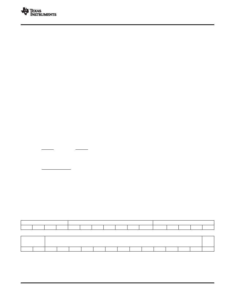
Register Address
Reference Frequency (Integer Part)
Refernece Frequency (Fractional Part)
DB0
DB1
DB2
DB3
DB4
DB5
DB6
DB7
DB8
DB9
DB10
DB11
DB12
DB13
DB14
DB15
Reference
VCO Frequency in MHz
START
Frequency
_CAL
Continued
DB16
DB17
DB18
DB19
DB20
DB21
DB22
DB23
DB24
DB25
DB26
DB27
DB28
DB29
DB30
DB31
Figure 85. Register 2
Copyright 2005–2008, Texas Instruments Incorporated
37
Product Folder Link(s): TRF3761
相关PDF资料 |
PDF描述 |
|---|---|
| TRF3761-AIRHAR | PLL FREQUENCY SYNTHESIZER, 104 MHz, PQCC40 |
| TRF3761-AIRHARG4 | PLL FREQUENCY SYNTHESIZER, 104 MHz, PQCC40 |
| TRF3761-AIRHAT | PLL FREQUENCY SYNTHESIZER, 104 MHz, PQCC40 |
| TRF3761-EIRHARG4 | PLL FREQUENCY SYNTHESIZER, 104 MHz, PQCC40 |
| TRF3761-DIRHAT | PLL FREQUENCY SYNTHESIZER, 104 MHz, PQCC40 |
相关代理商/技术参数 |
参数描述 |
|---|---|
| TRF3761-BIRHATG4 | 功能描述:时钟合成器/抖动清除器 Low Noise Integer N PLL Freq Synth RoHS:否 制造商:Skyworks Solutions, Inc. 输出端数量: 输出电平: 最大输出频率: 输入电平: 最大输入频率:6.1 GHz 电源电压-最大:3.3 V 电源电压-最小:2.7 V 封装 / 箱体:TSSOP-28 封装:Reel |
| TRF3761-C | 制造商:TI 制造商全称:Texas Instruments 功能描述:INTEGER-N PLL WITH INTEGRATED VCO |
| TRF3761-CIRHAR | 功能描述:时钟合成器/抖动清除器 Low Noise Integer N PLL Freq Synth RoHS:否 制造商:Skyworks Solutions, Inc. 输出端数量: 输出电平: 最大输出频率: 输入电平: 最大输入频率:6.1 GHz 电源电压-最大:3.3 V 电源电压-最小:2.7 V 封装 / 箱体:TSSOP-28 封装:Reel |
| TRF3761-CIRHARG4 | 功能描述:时钟合成器/抖动清除器 Low Noise Integer N PLL Freq Synth RoHS:否 制造商:Skyworks Solutions, Inc. 输出端数量: 输出电平: 最大输出频率: 输入电平: 最大输入频率:6.1 GHz 电源电压-最大:3.3 V 电源电压-最小:2.7 V 封装 / 箱体:TSSOP-28 封装:Reel |
| TRF3761-CIRHAT | 功能描述:时钟合成器/抖动清除器 Low Noise Integer N PLL Freq Synth RoHS:否 制造商:Skyworks Solutions, Inc. 输出端数量: 输出电平: 最大输出频率: 输入电平: 最大输入频率:6.1 GHz 电源电压-最大:3.3 V 电源电压-最小:2.7 V 封装 / 箱体:TSSOP-28 封装:Reel |
发布紧急采购,3分钟左右您将得到回复。